Engine
This engine was not a hard decision for me to make, I know the majority of builders opt for the Chevy route and this is fine for them,
however I’m after a slightly more authentic look under the bonnet, so this leads me down the Ford route. This then leaves a few
choices, however as previously stated this is paying tribute to the amazing car Nigel Dean built, so it had to be a Ford 351 Cleveland,
an American V8 only built for 5 years from 1970 to 1975, so not too hard to find ?
After spending ages checking and checking eBay, Piston heads, etc, eventually I found one for sale in November 2006 in the free ads, it was lurking at the back of a garage in Cardiff, so I called the guy up and agreed on a price for me to collect the next weekend. I hired a van and collected. All I can say is that the 351C block complete with FMX auto gearbox was probably the limit for the knackered old X-Reg transit I hired, mind you it was only Ł50 for the day! One thing I wish I had of done was to get some sort of recipt as I now have nothing to show when the IVA comes.
Once home the engine was chained to the engine crane and lifted out of the van, dragged into the garage and placed on a pallet – which it
promptly fell through and settled. It then sat there for about 3 months till I had the engine and gearbox removed from the Donor car for the project, the
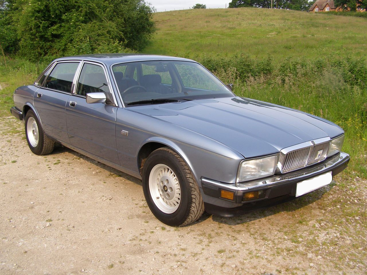
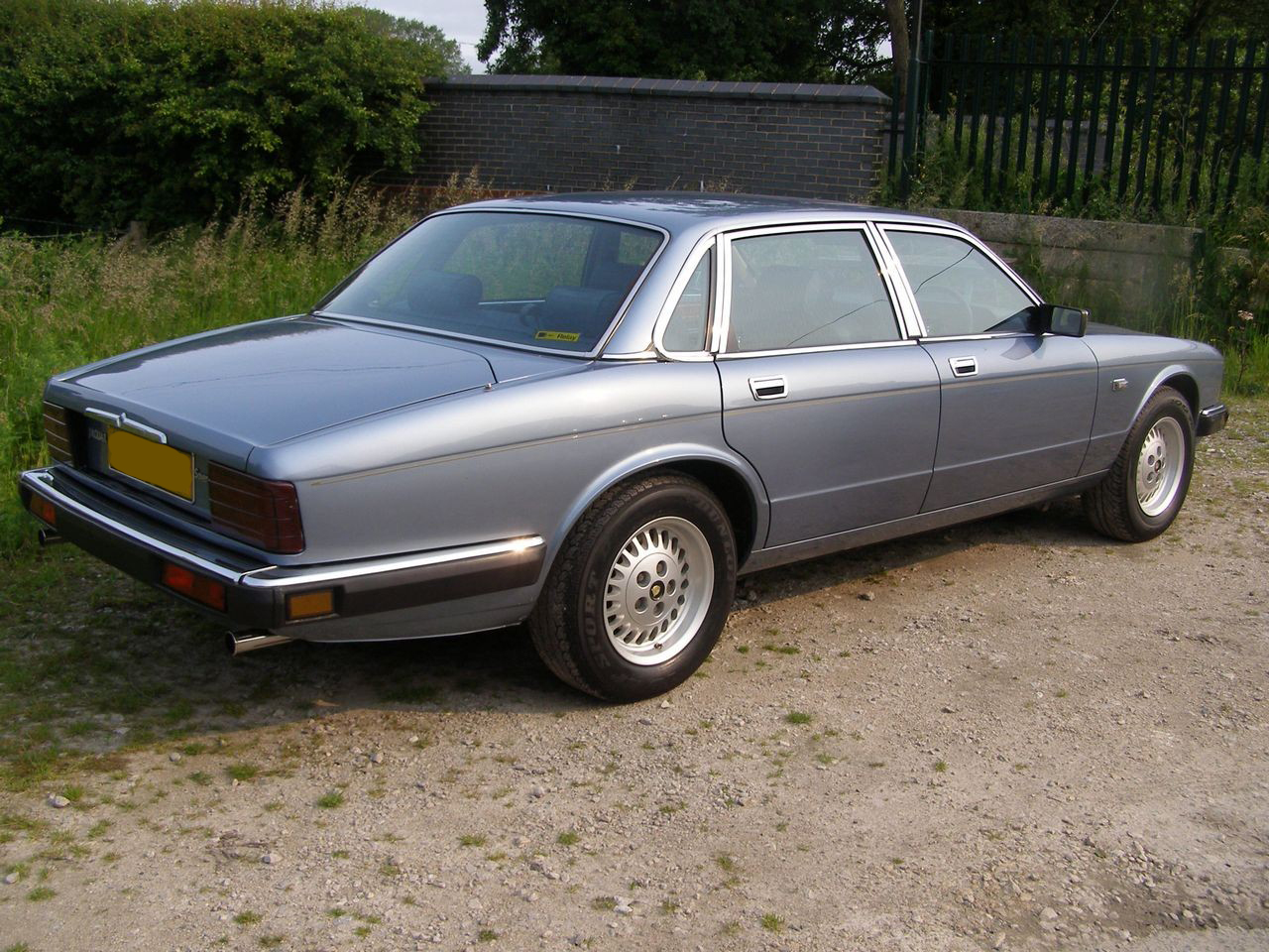
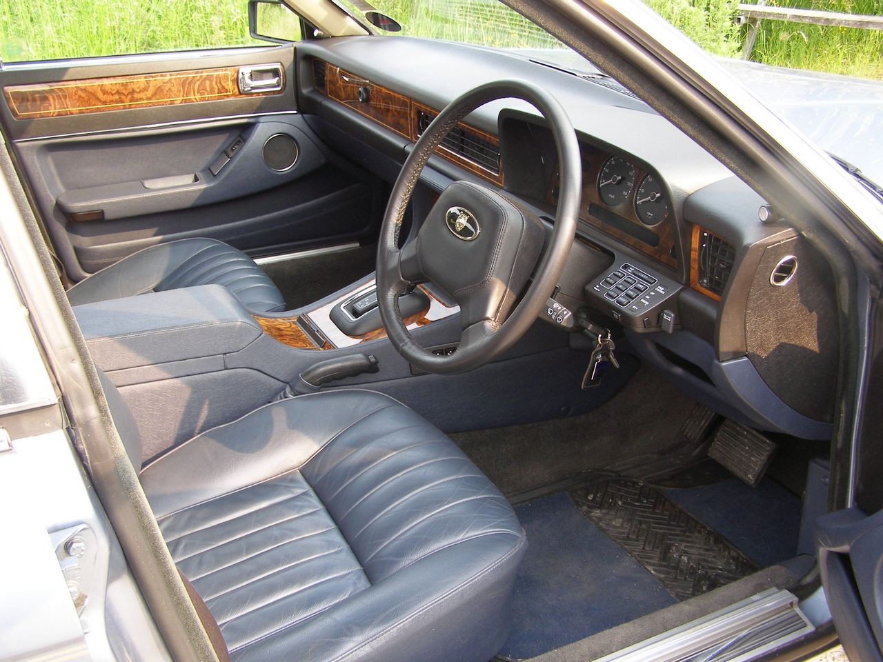
Jaguar XJ40, I bought this car way back in March 2004 as I knew which ever kit I ended up doing it was very likely to be Jaguar based.
With some very basic welding and simple mounts the V8 was installed into the Jag engine bay and with the bonnet removed
(as it didn’t fit anymore with the carb) the old V8 was treated to a new sump gasket, new plugs and some fresh oil. She was then connected to the Jag's battery,
exhaust and fuel tank and test fired. She ran ok - well not too bad for an engine that hadn’t been run in god knows how long. This wasn’t going to be
an issue as the whole engine will be stripped down and rebuild for the Cobra. It did prove that she ran and the block was sound. The engine then sat in the
Jag for the next couple of years till I was ready to start the kit.
Sadly there are no pictures of these initial stages of the engine rebuild as these have been lost prior to the start of the website, all I have are a couple of
shots of the fantastic XJ40 donor, worth every penny of the Ł400 asking price !
The story of the engine as far as the kit car is conernced now starts after the engine was removed again from the Jag.
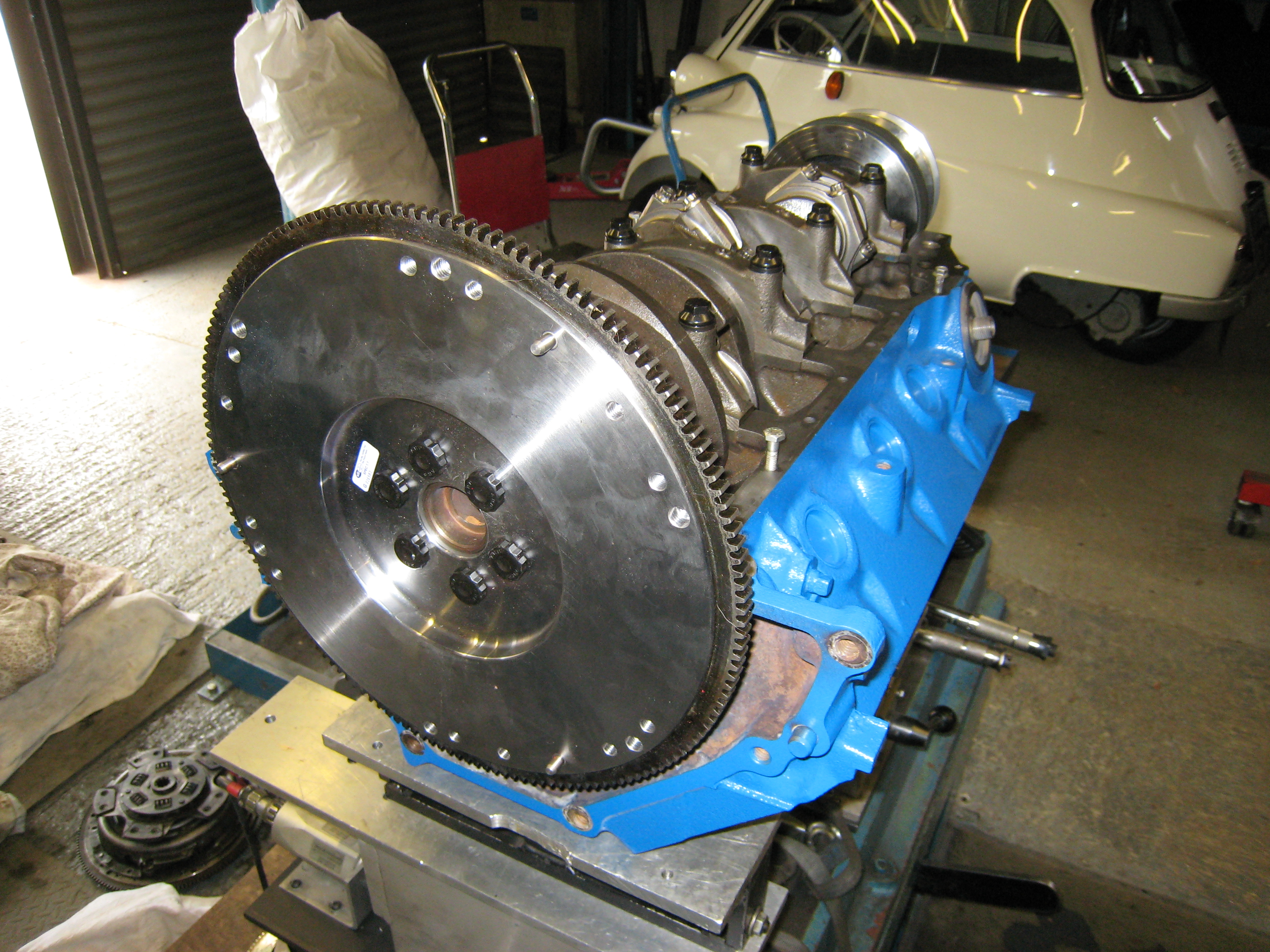
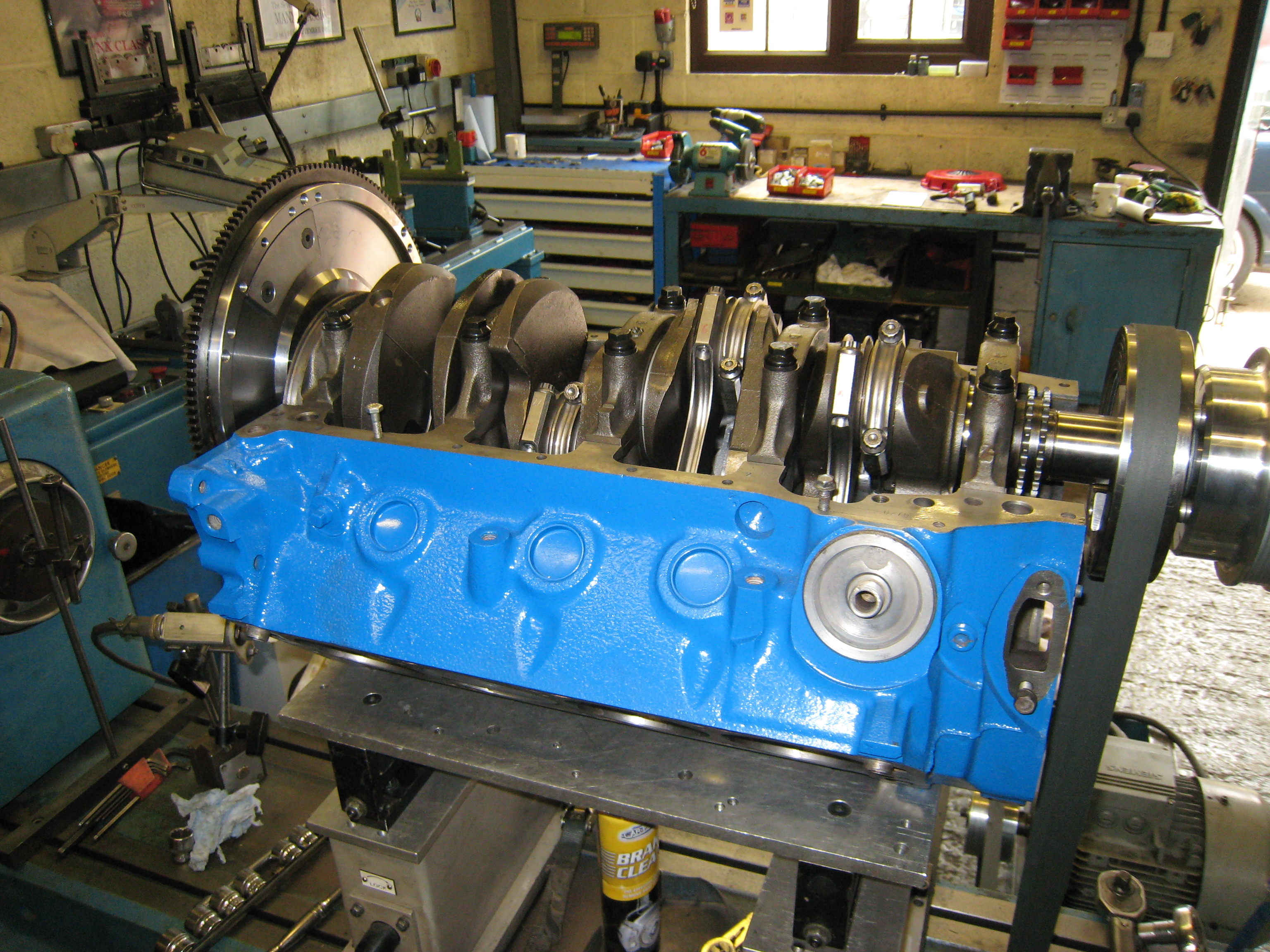
The pictorial story starts after the block has been stripped, chemically cleaned and bored out +0.030". Cleaned again and painted.
![]()
Once all the bottom end components had been inspected and checked it was time to get the engine balanced, the only original bottom end
part was the crank that had be reground -0.010" and new larger bearings purchased and held in place with ARP bolts. The bottom end
rebuild consists of :-
| New Flywheel | This was originally an auto so only had a flex plate | Part of Gearbox Package |
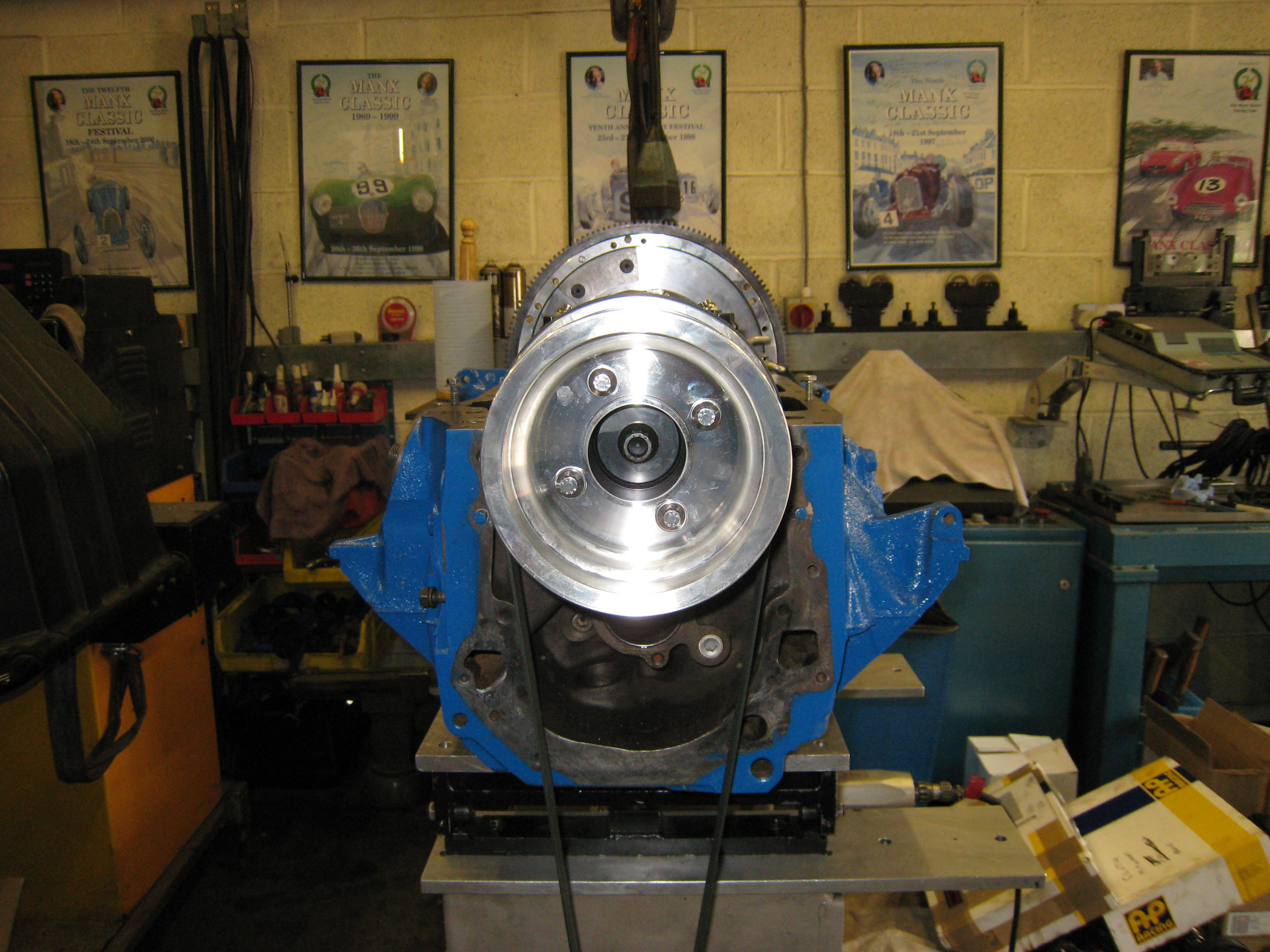
| New Harmonic Balancer | Pro Race | 34269 |
| New Bottom Pulley | March Serpentine Set | 1670 |
| New Timing Set | Edelbrock | 7821 |
| New Con Rods | Eagle H beam | CRS5780F3D |
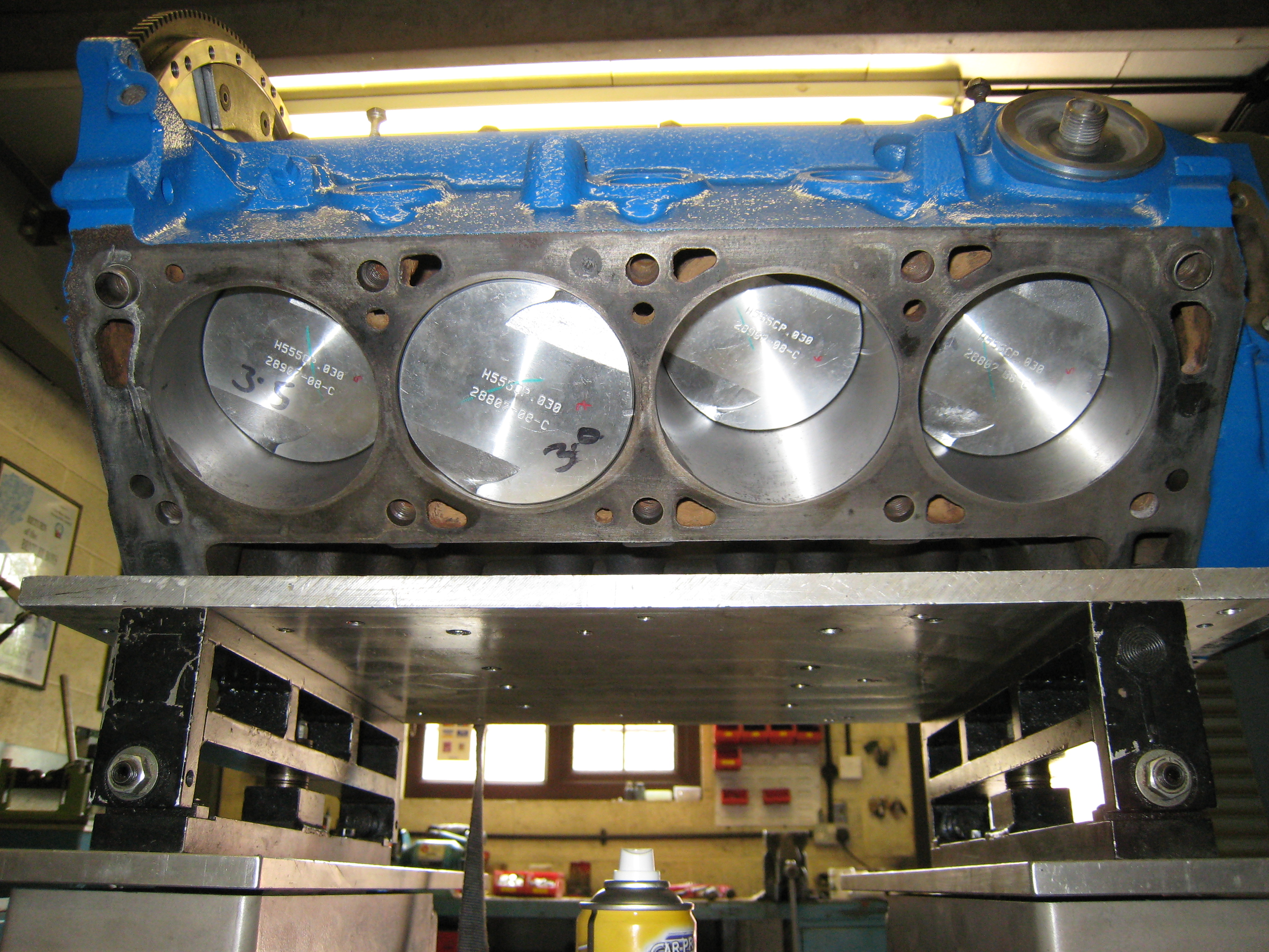
| New Pistons | Speed Pro | ZWL2379F30 |
| New Rings | Perfect Circle | ???? |
The next photos show the block as it is being prepared for balancing.
The balancing its self is an interesting process, my description is only a very basic outline of what actually took the best part of 3/4
of a day to achieve. The fantastic people at
Vibration Free
were very patient with me as I watched every stage of the process, I did manage to actually do something useful and get involved
though, by making the tea!
Each piston/con rod assembly was weighed to the nearest 10th of a gram,
the lightest found and then the others had the waste material on the skirt of the piston ground down till they all weighed the same.
The piston rings were weighed but not installed to reduce friction, instead equivalent weights were glued to the tops of the pistons.
The whole assembly was assembled with plenty of oil and strapped to the balancing table.
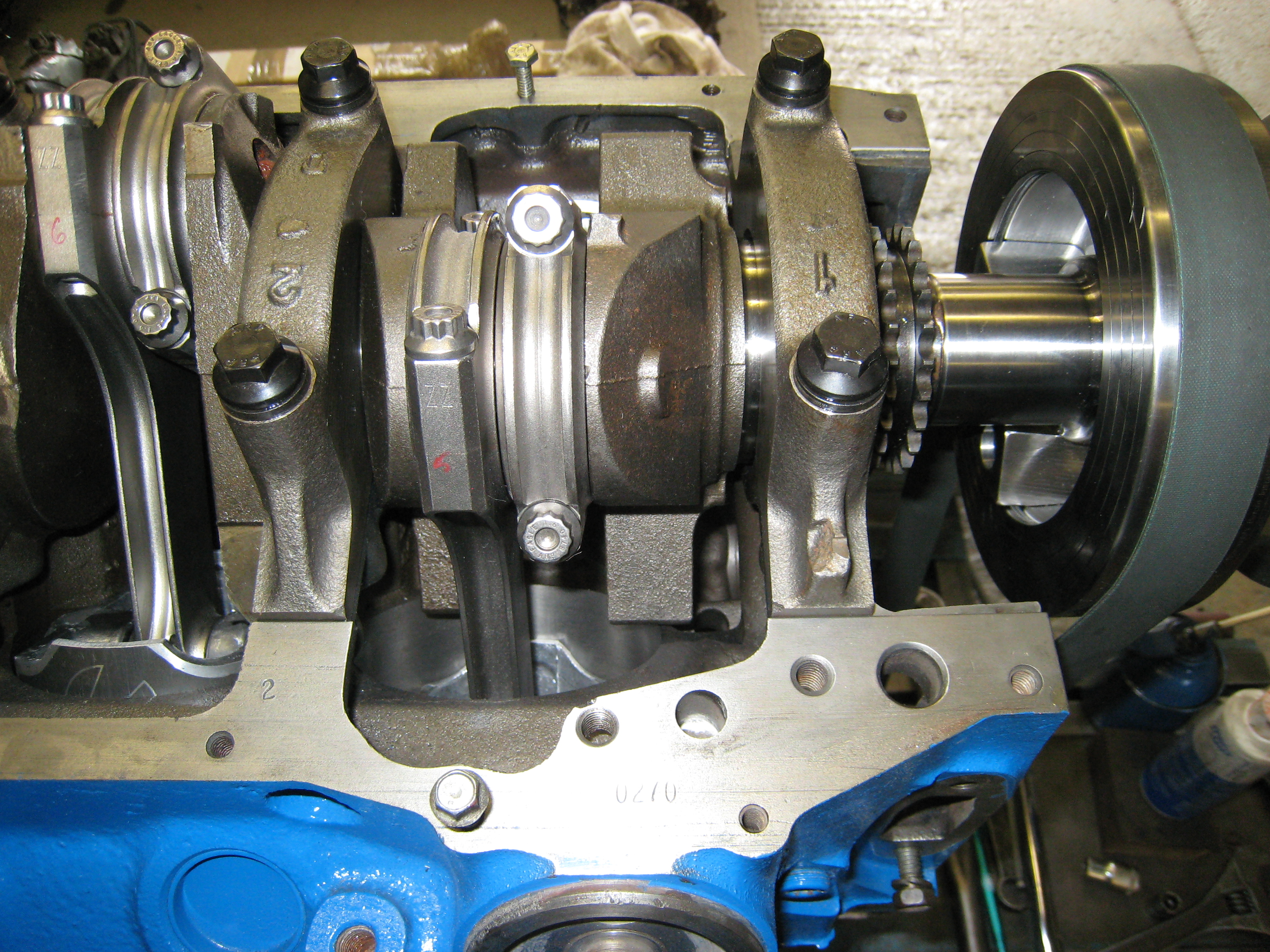
The next step was to assemble the short block and mount it on the working table, connect the balancer to a electric
motor and spin the assembly to see how much it shook !. The squeaking and whining noise you can hear are the rollers of
The tables belt drive and the electric motors inverter.
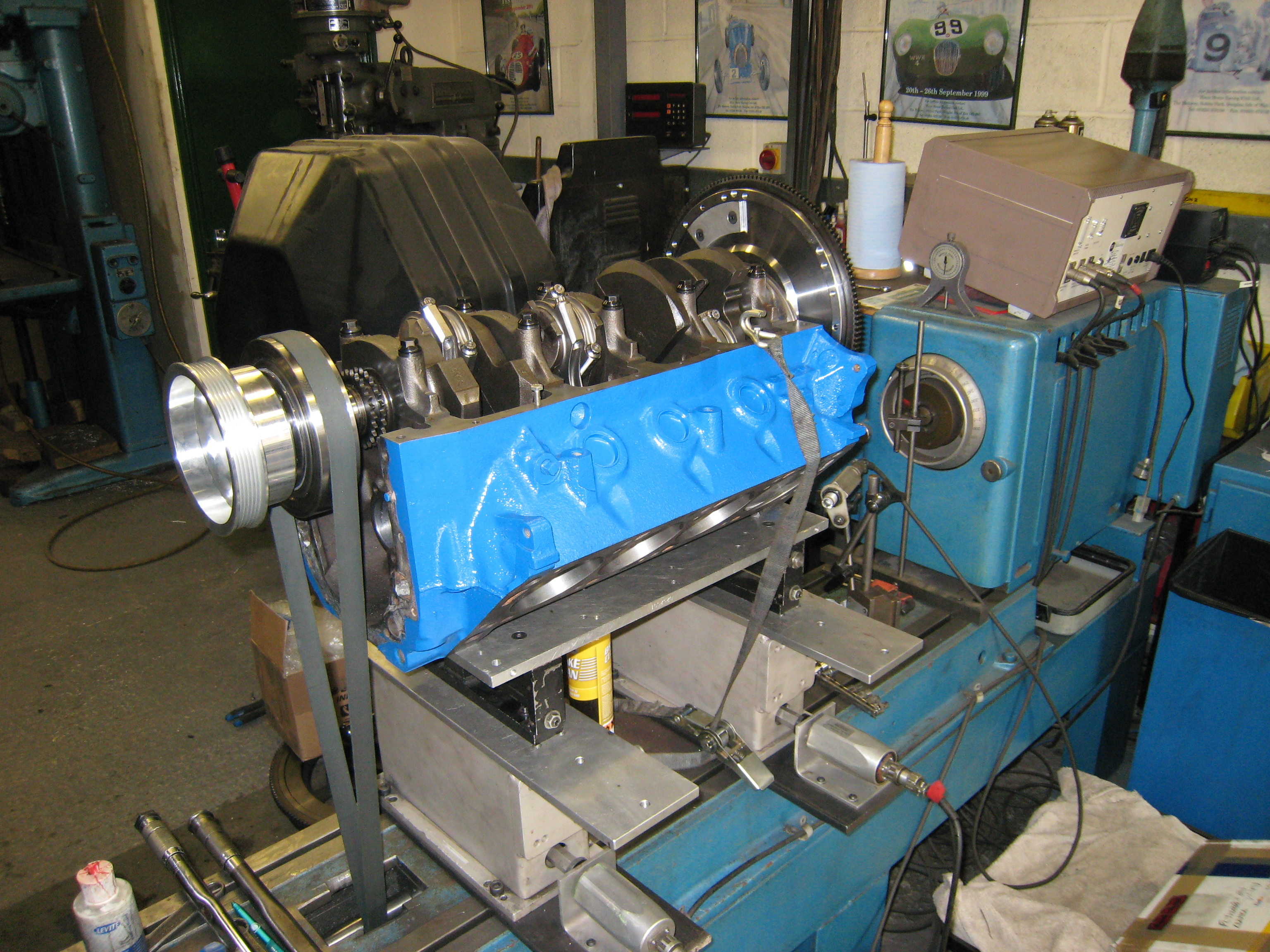
The next step was spin the assembly at a higher speed and assess the imbalance of the rotating assembly.
This is done at about 500 rpm. The readings from the balancer are then used to calculate the amount of
material to be removed from the harmonic balancer and/or the fly wheel. In my case it was material removal
from both.
This was the first time in a really long time that the engine had turned at any speed other than by hand. But once complete
I have an engine that should rev smoothly and not shake itself to bits.
The now balanced engine was totally striped and everything checked, there was no sign of wear at all from the balancing
process which was a relief. The short motor was now assembled for the last time, everything torqued down and oiled.
The short block then sat for a while whilst the next few components were purchased. Next major purchase
were the
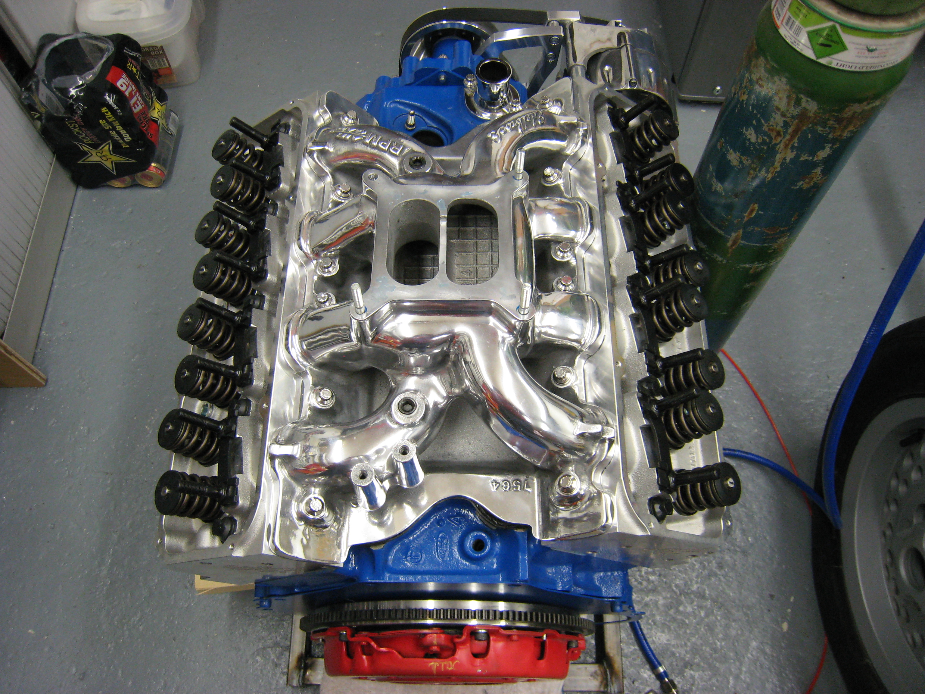
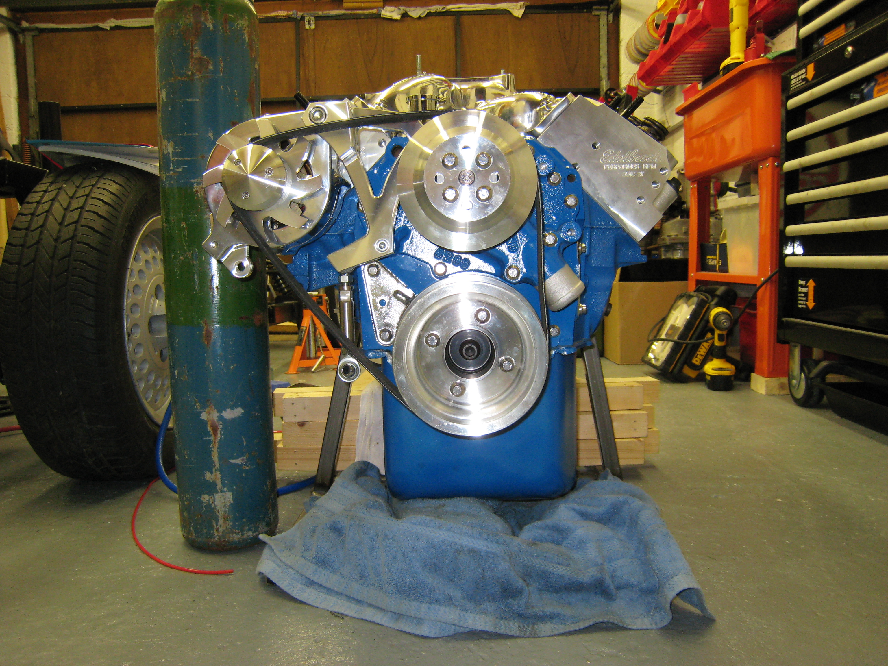
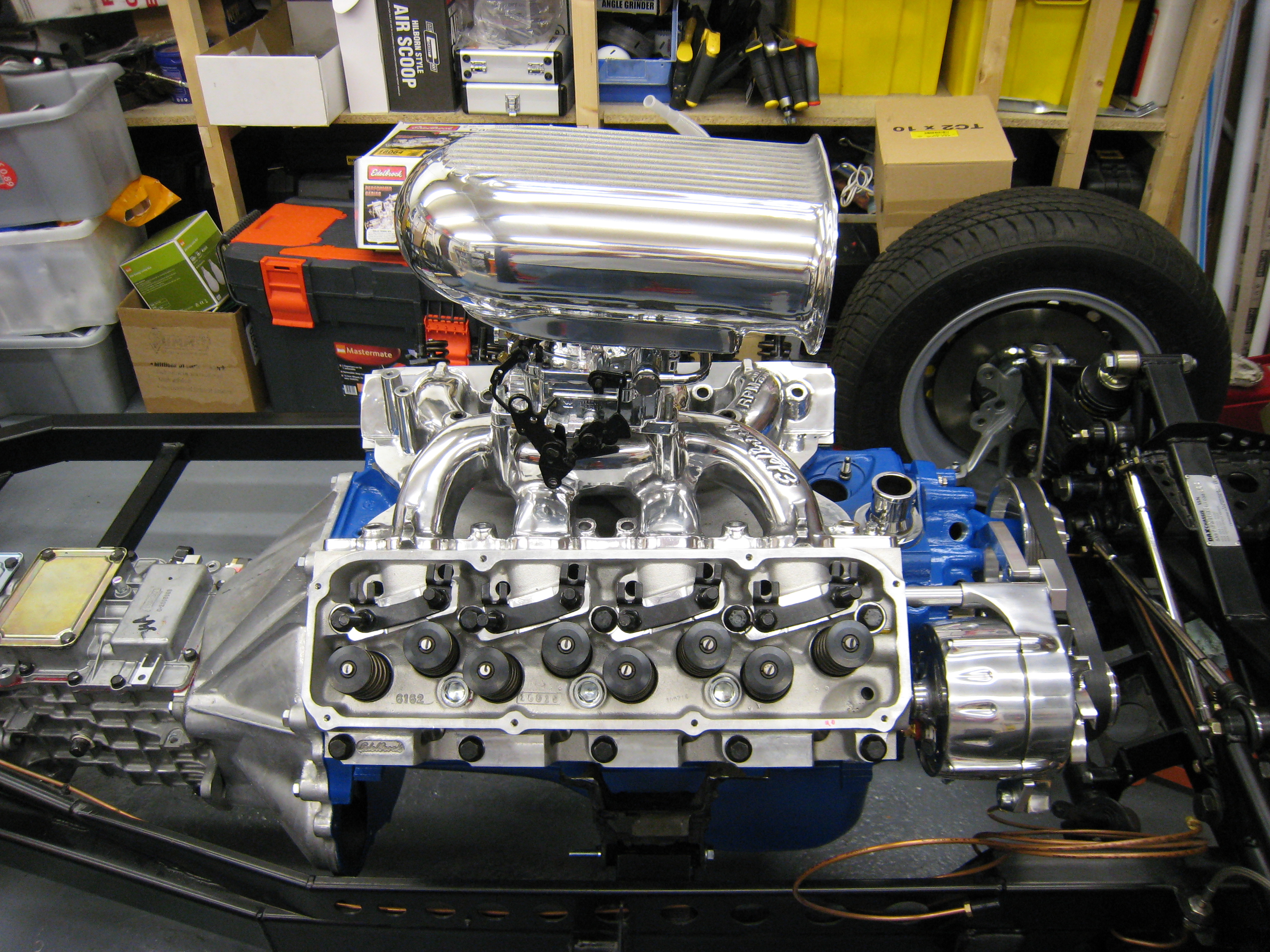
Edelbrock Heads [61629] these look so good that they had to go straight on ! Next came the
Edelbrock Inlet Manifold [7564], this was only available as a cast finished, so a trip to the polishers
had this looking nice and shiny too.
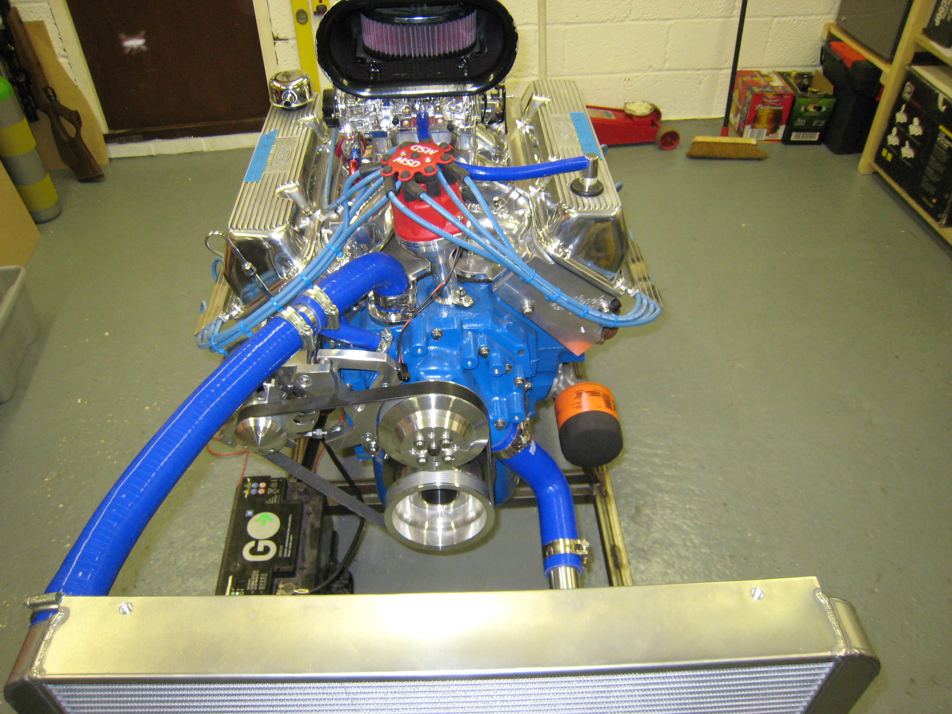
I also purchased a chrome alternator and billet aluminium pulley set, so that HAD to go on just to see how it looked,
and to be honest I'm very impressed with how its turned out.
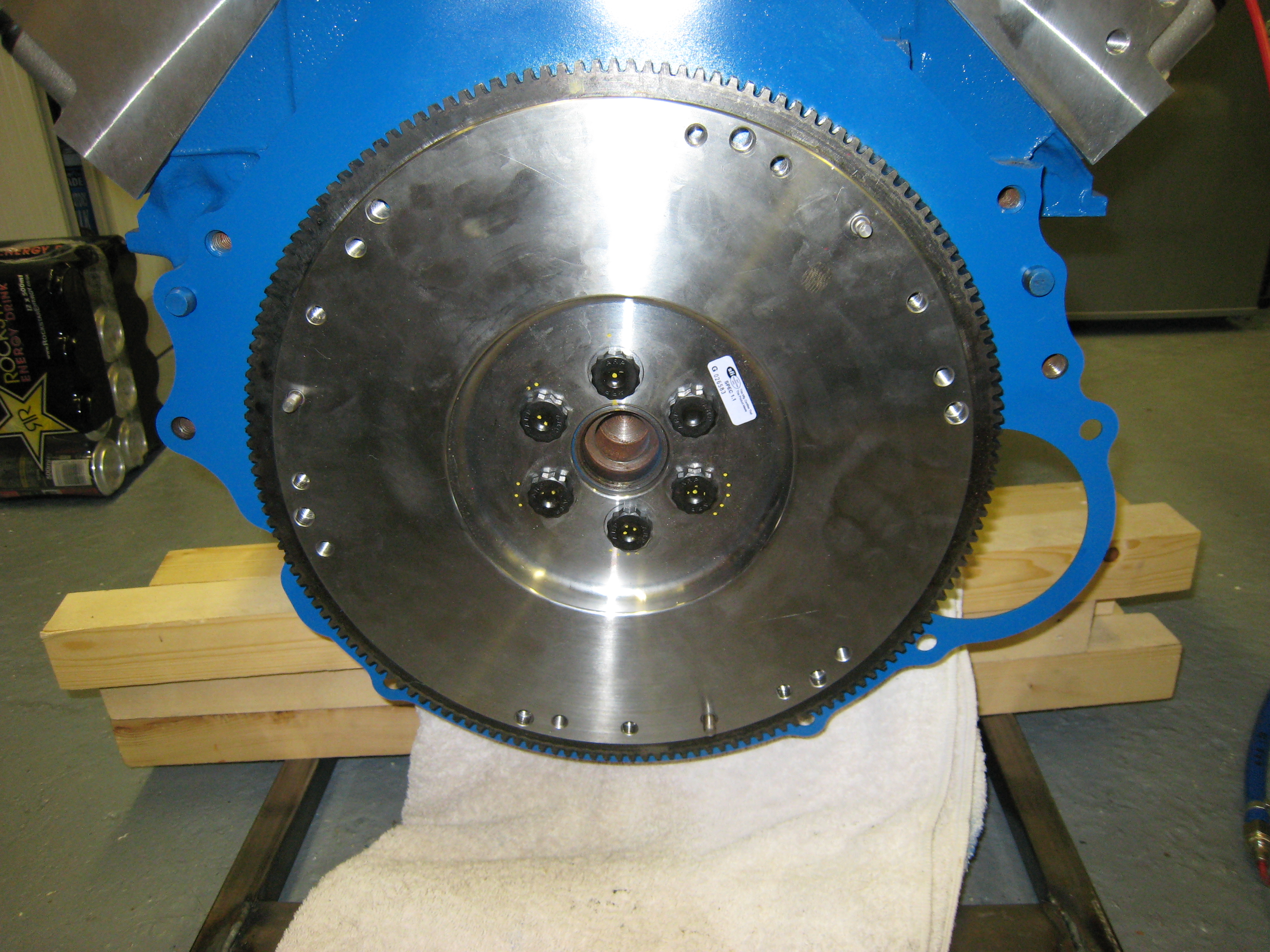
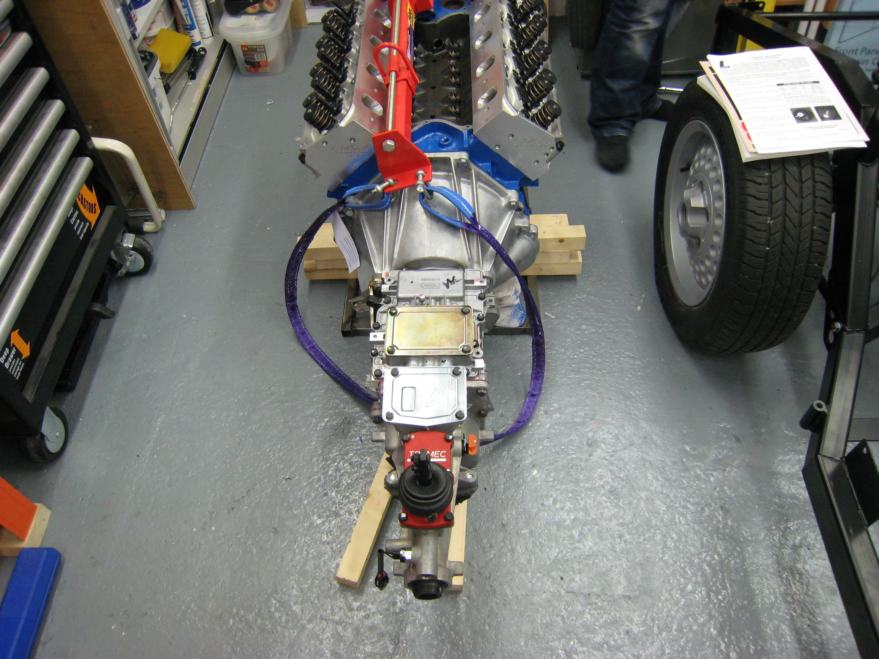
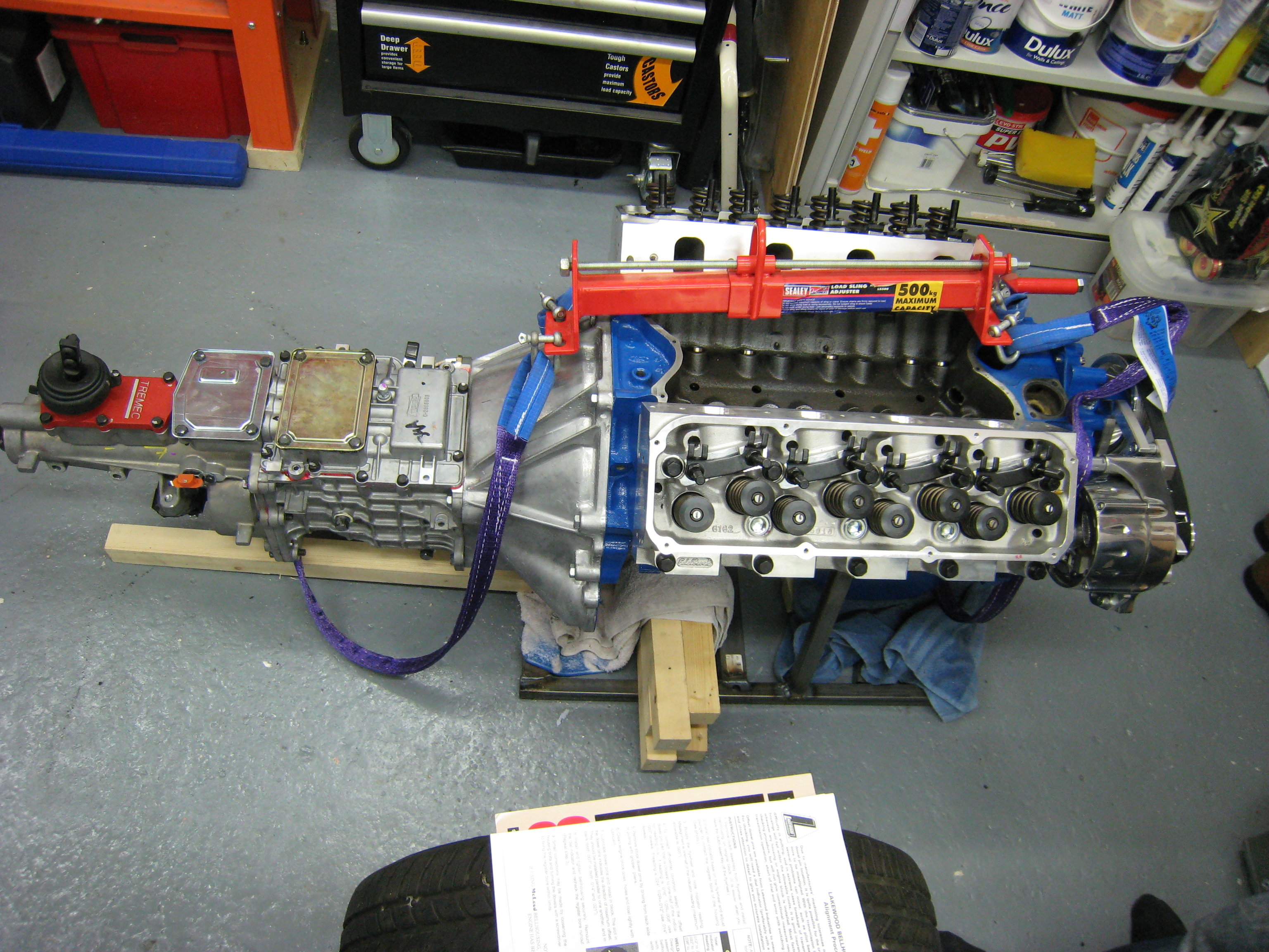
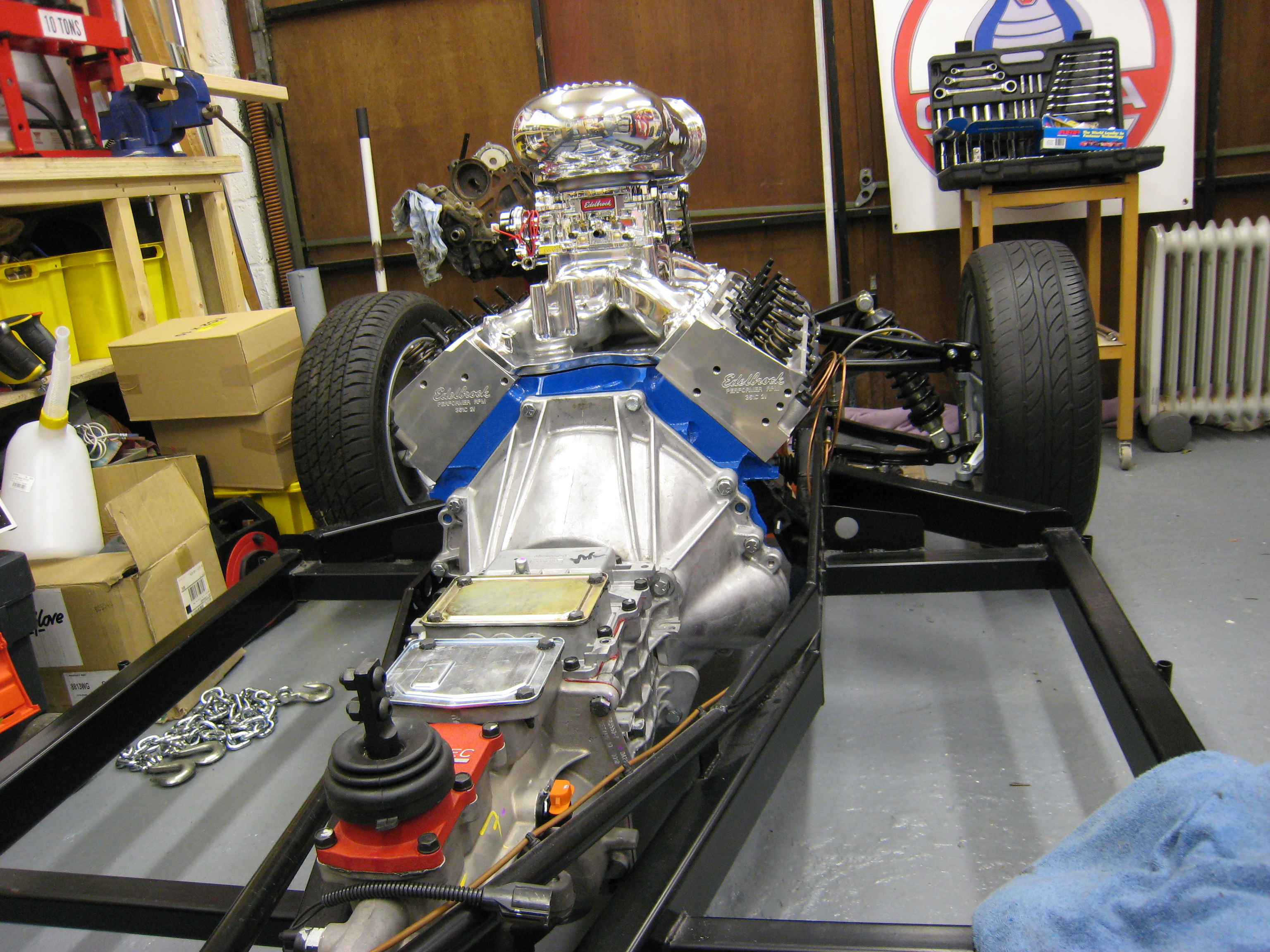
Time for the McLeod clutch assembly.
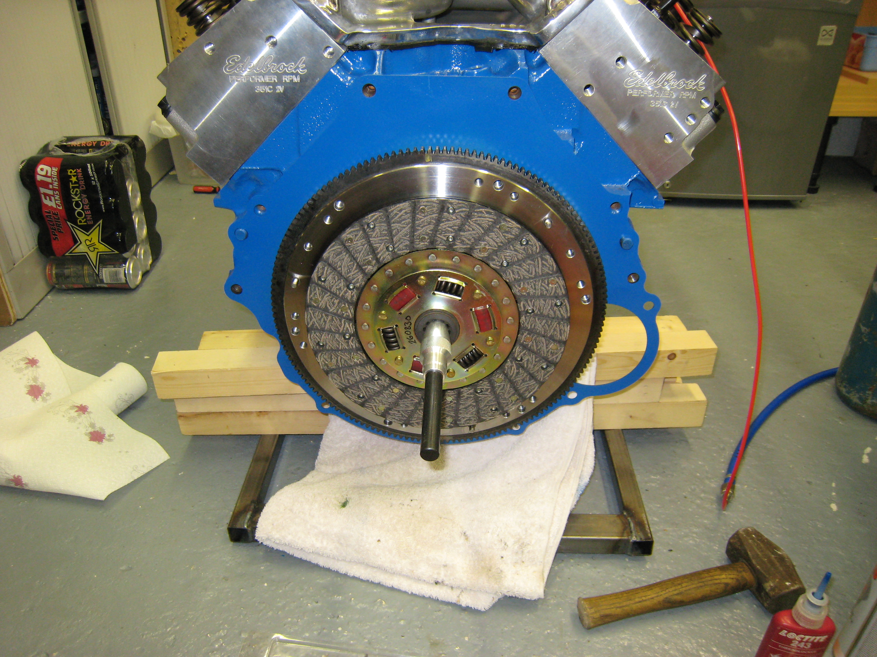
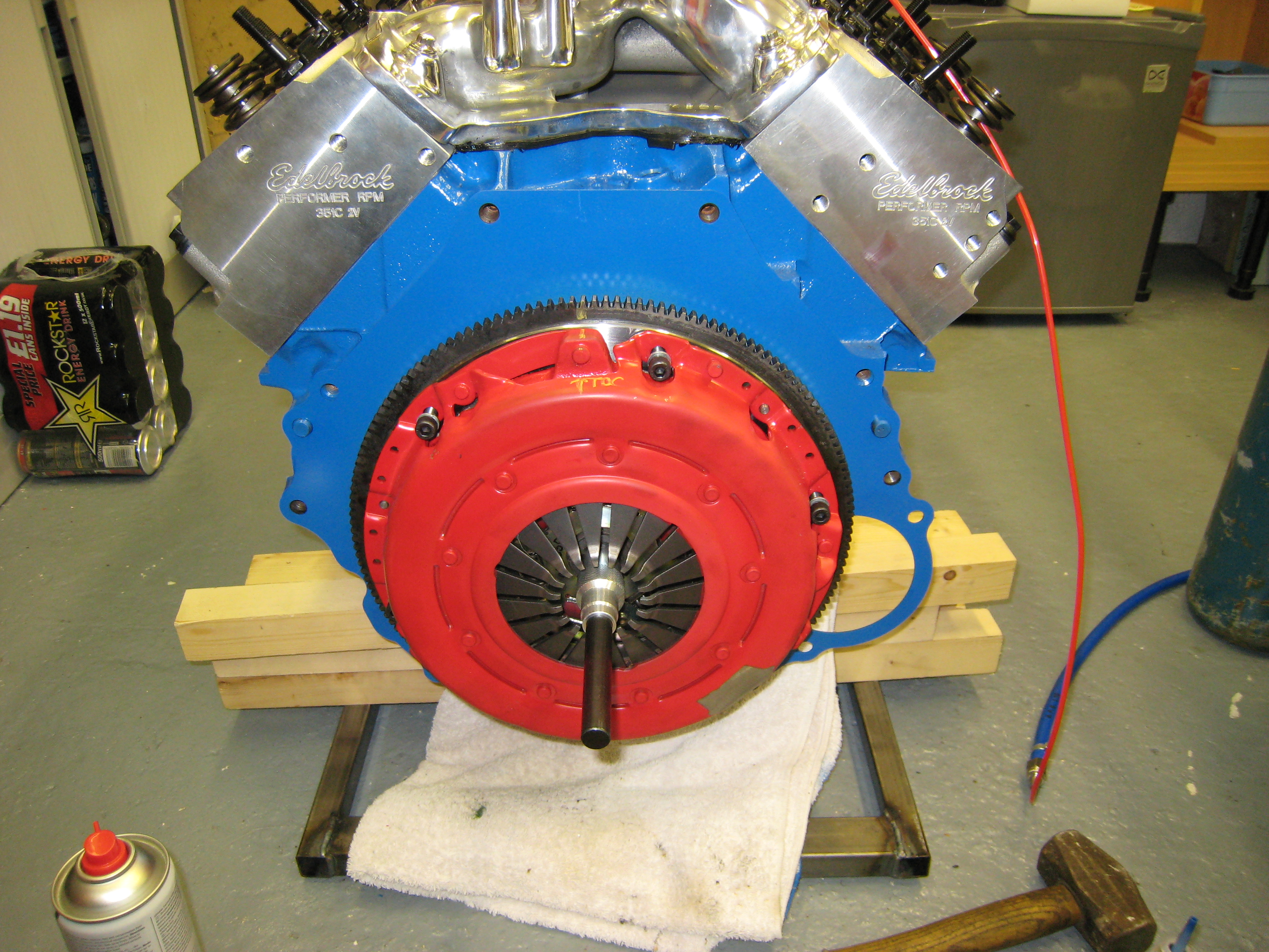
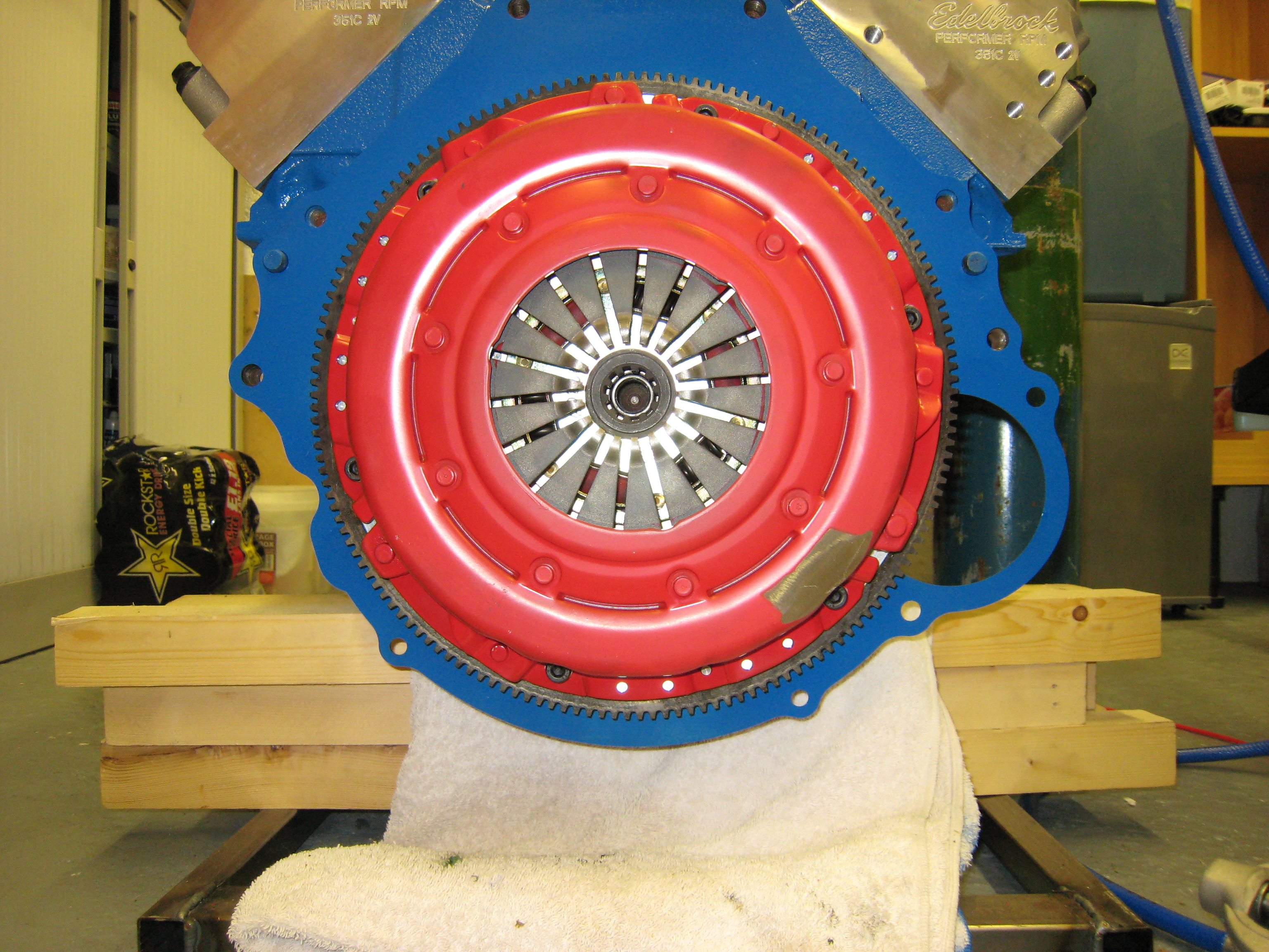
Prior to fitting the gearbox the tolerances were checked against the bell housing manufactures
specification for alignment. As it turned out the max limit was 0.005" and mine came in at 0.0025"
so well within. Now to mate the Engine and gearbox, quite a bit of huffing and puffing and then
the box was on.
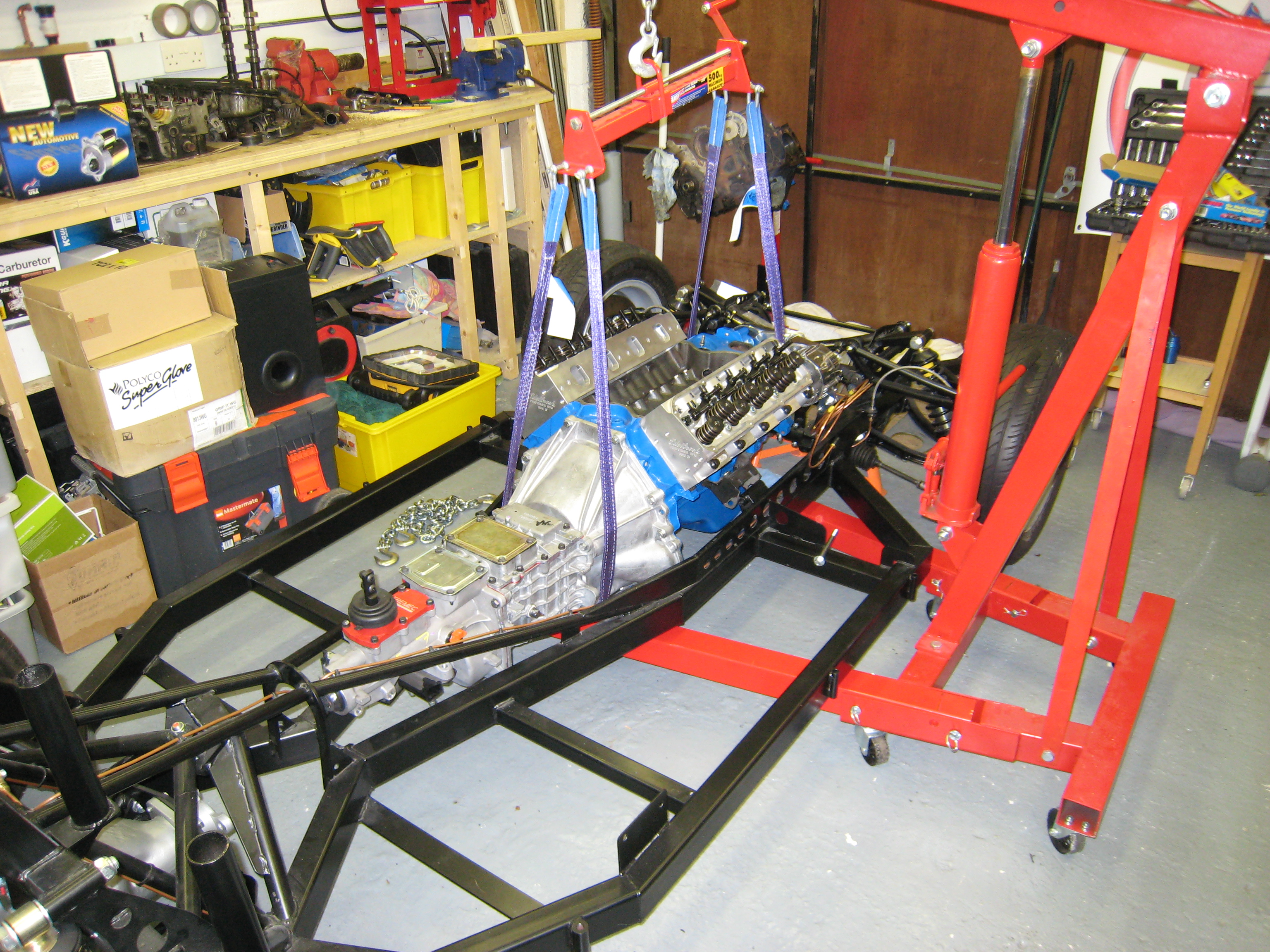
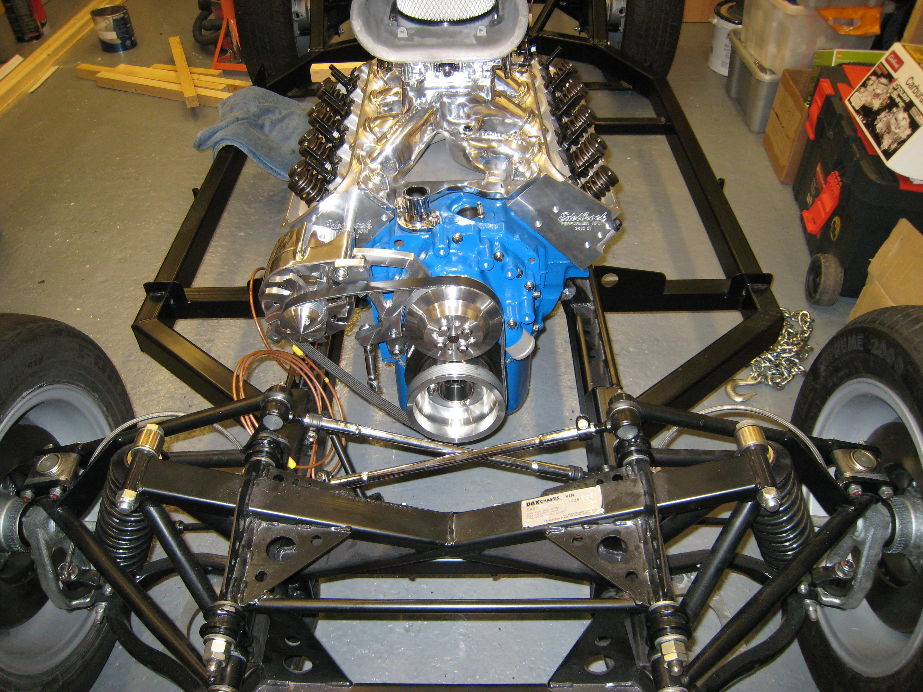
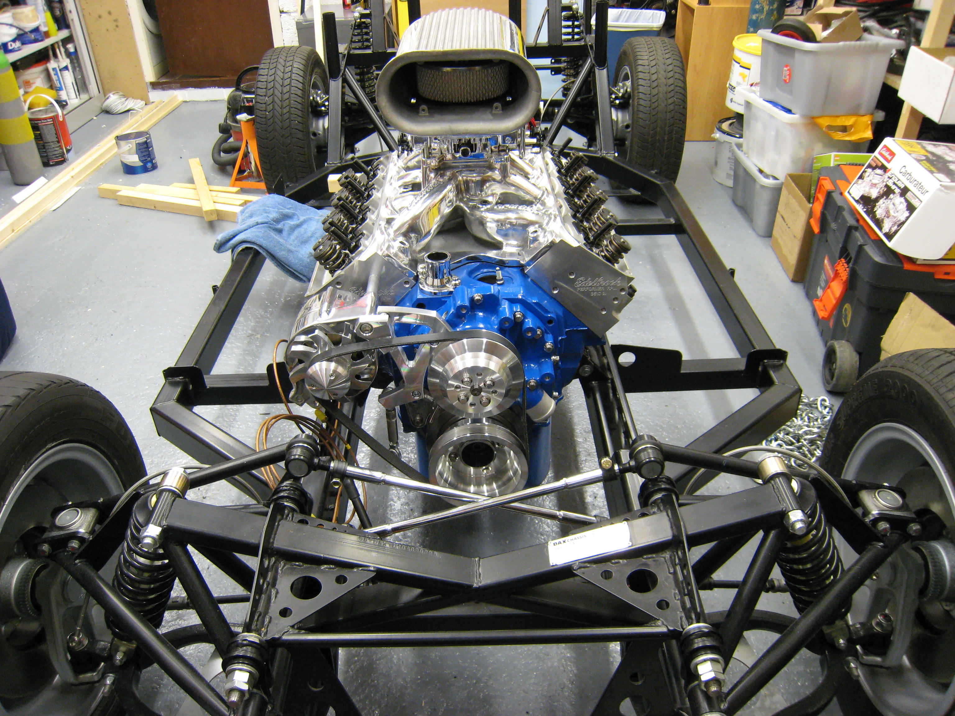
Now following the advise of more than a few people, I tried test fitting the engine, good job I
did as there is a slight alignment issue (25mm) with the chassis and mounts. This I hope to resolve
over the next couple of days with Dax.
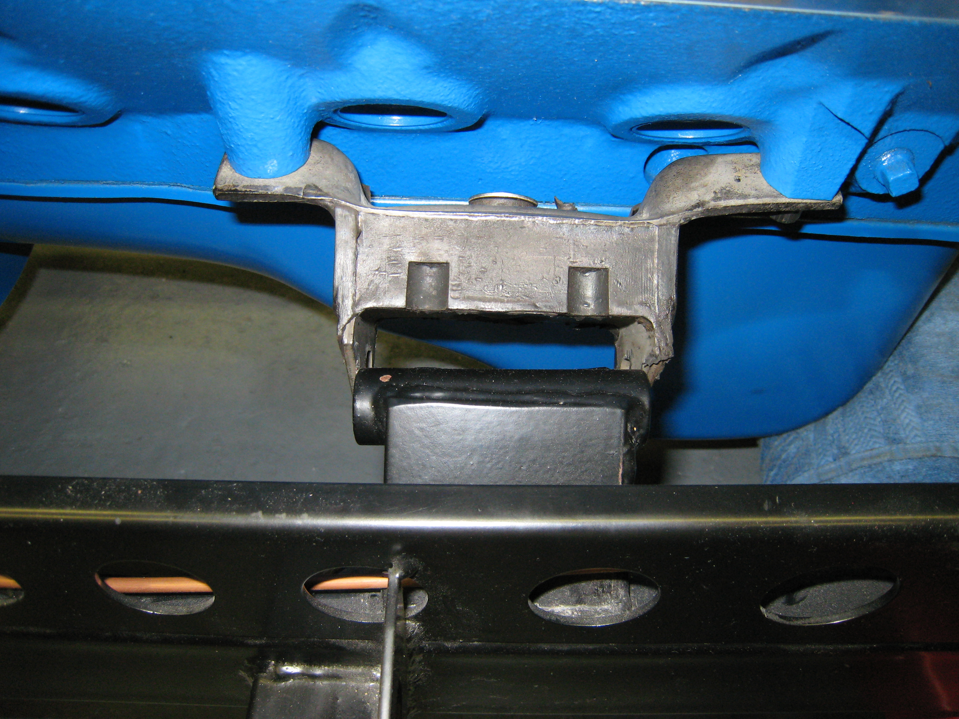
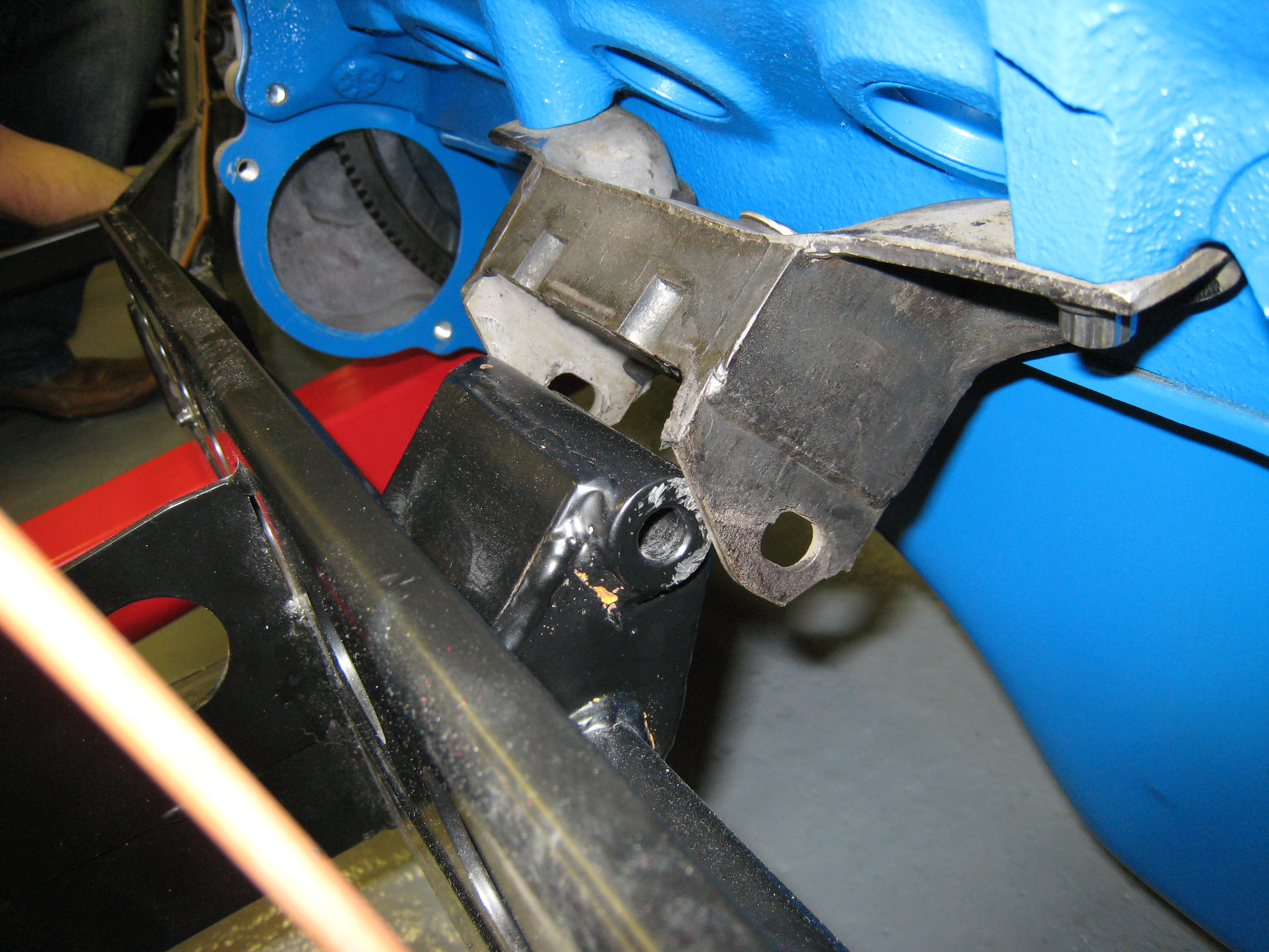
A couple of photos showing the passenger side mount in place and the shortfall of the drivers side.
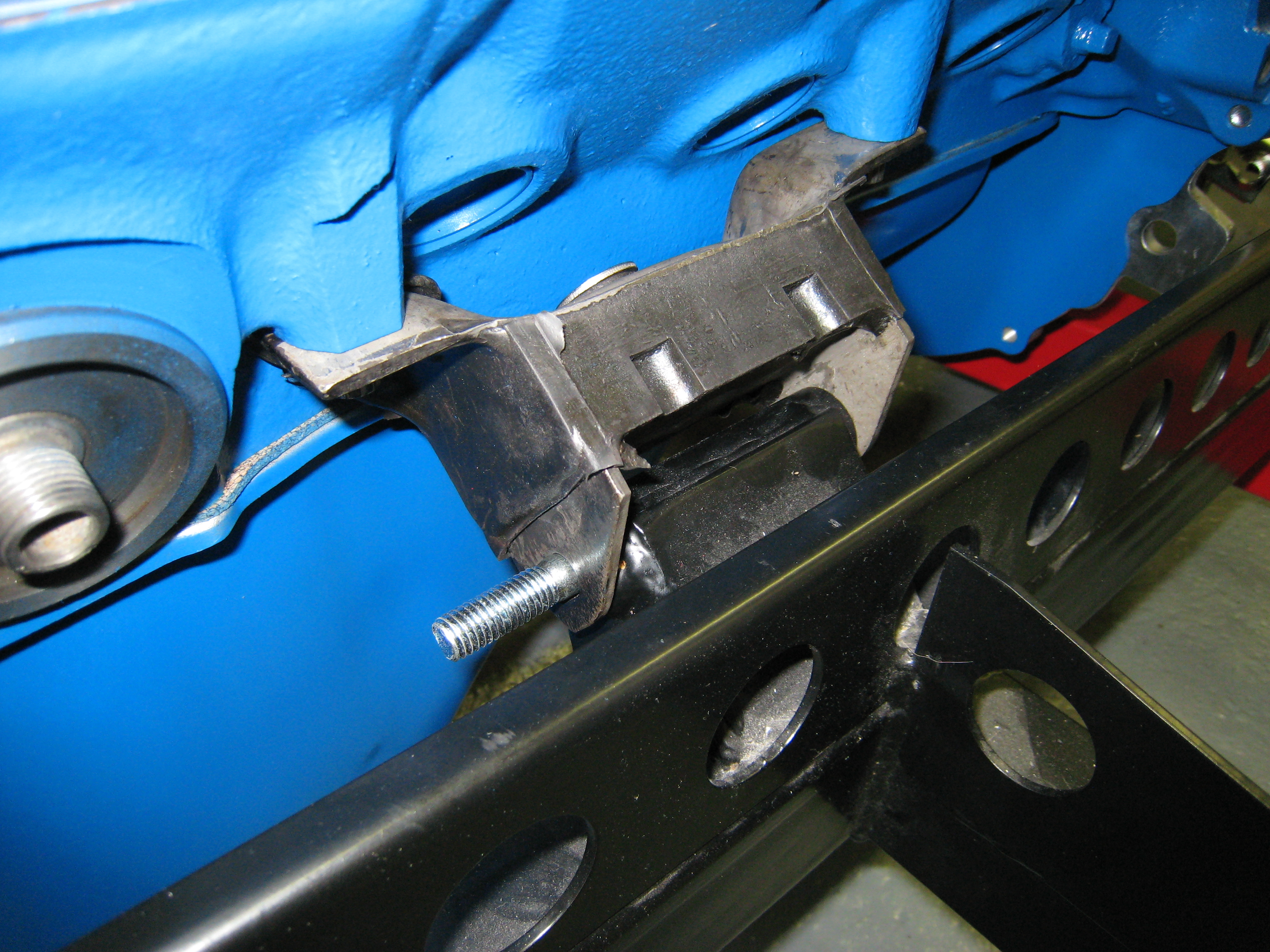
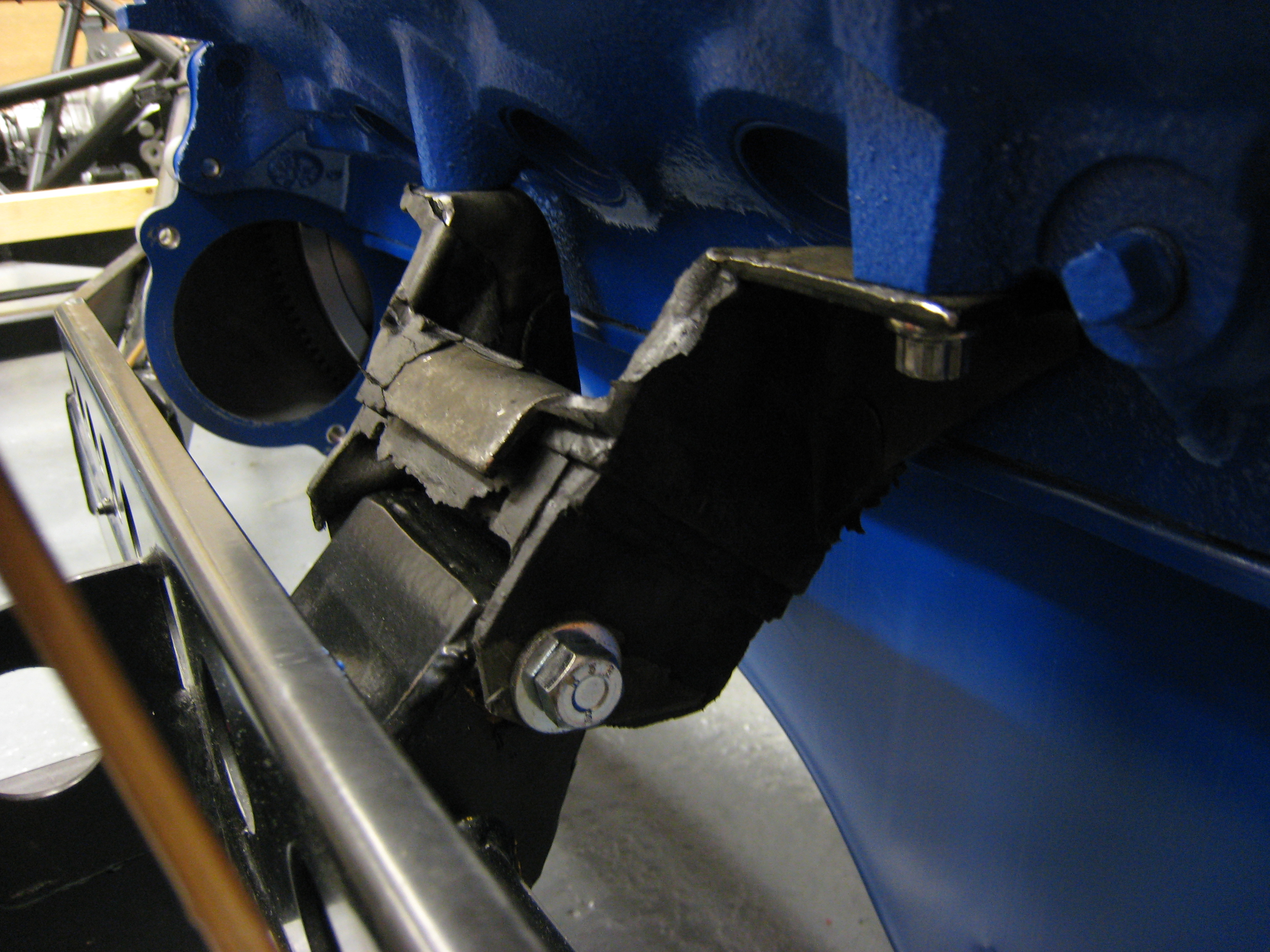
Having spoken to Peter at Dax the issue of the mounts is resolved as simply as replacing the supplied
ones with the correct ones, for the record the correct mounts are the "Roadcraft" ones. Couple of pics
showing the new mount in place and then I couldn't resist fitting some of the shiny bits on.
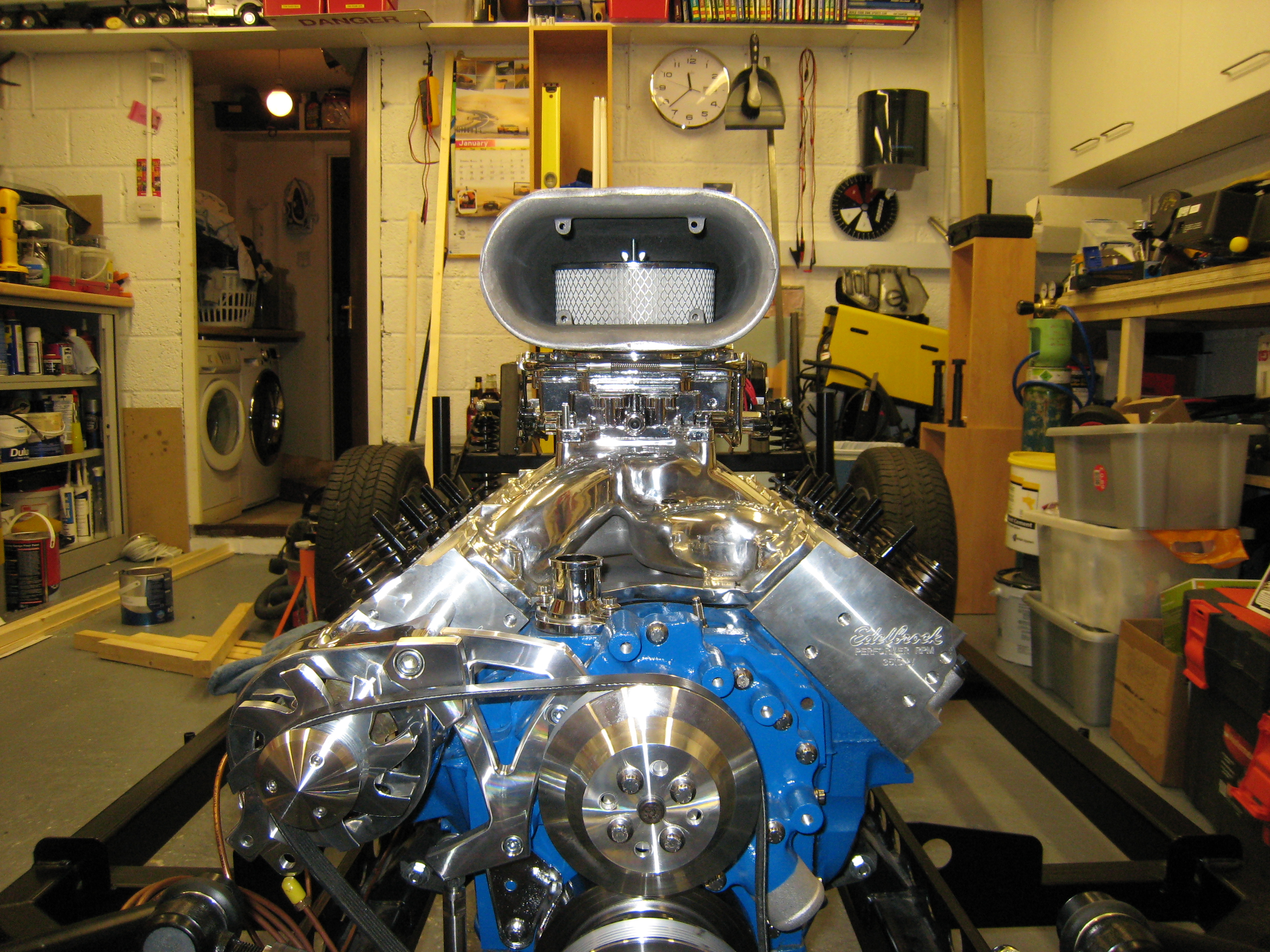
Now the engine was in the chassis I couldnt resist connecting up the starter motor and turning her over.
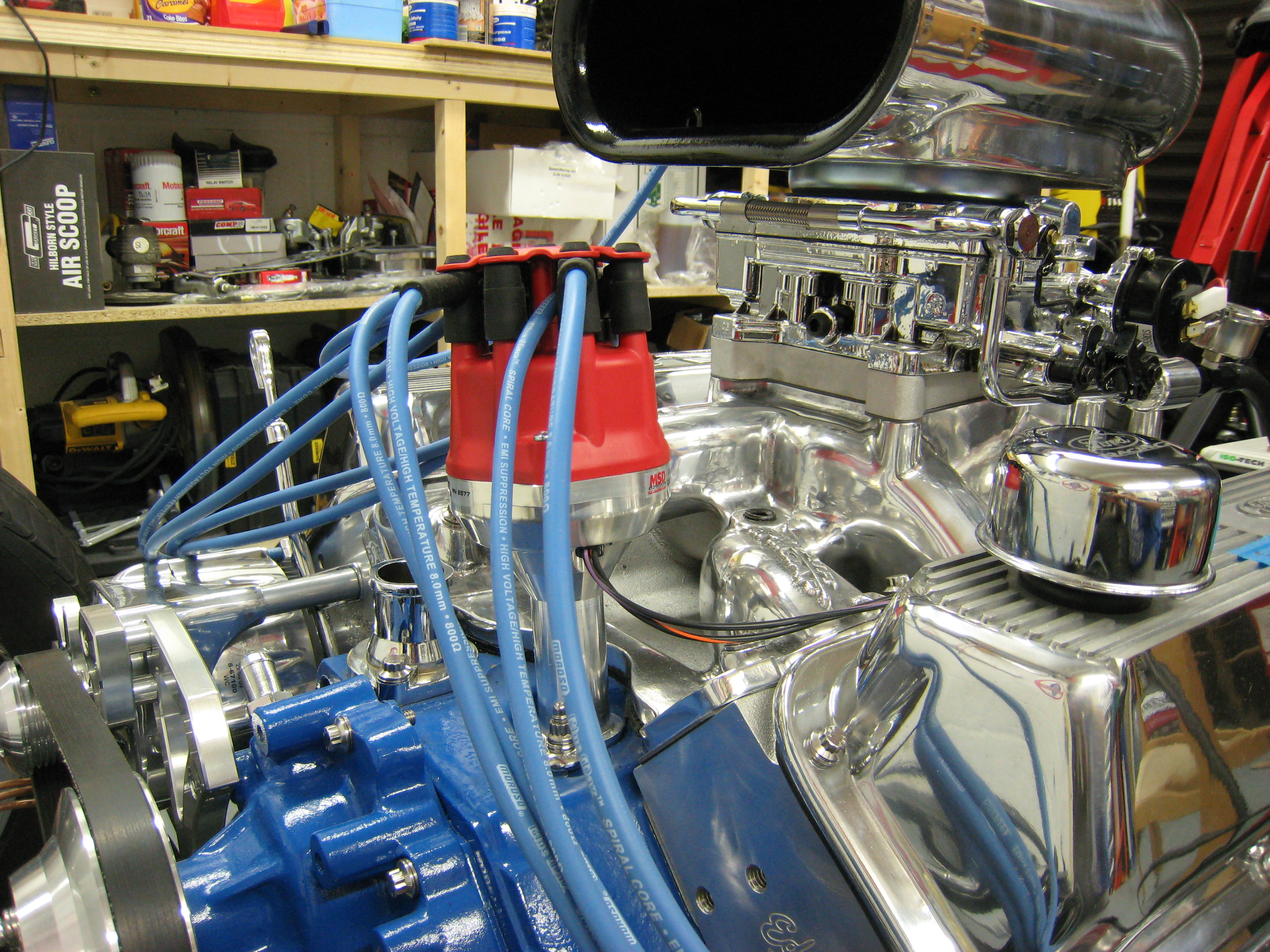
Also noticed that the carb was sat a a funny angle, turns out that in the original Mustang the engine actually
sits arse down, so I'll need a wedge plate to level it up. Also tried on the dizzy just to see how it looks.
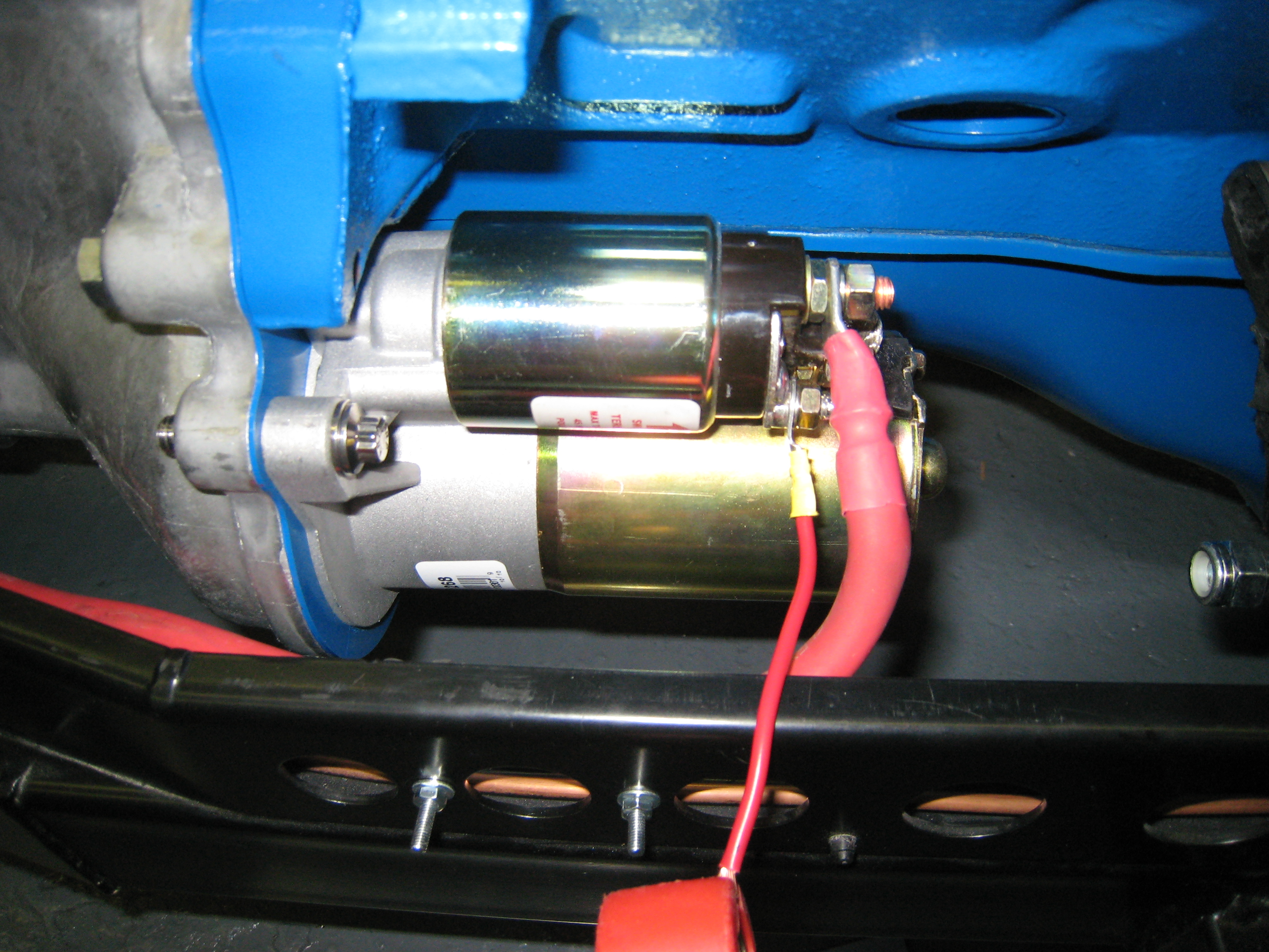
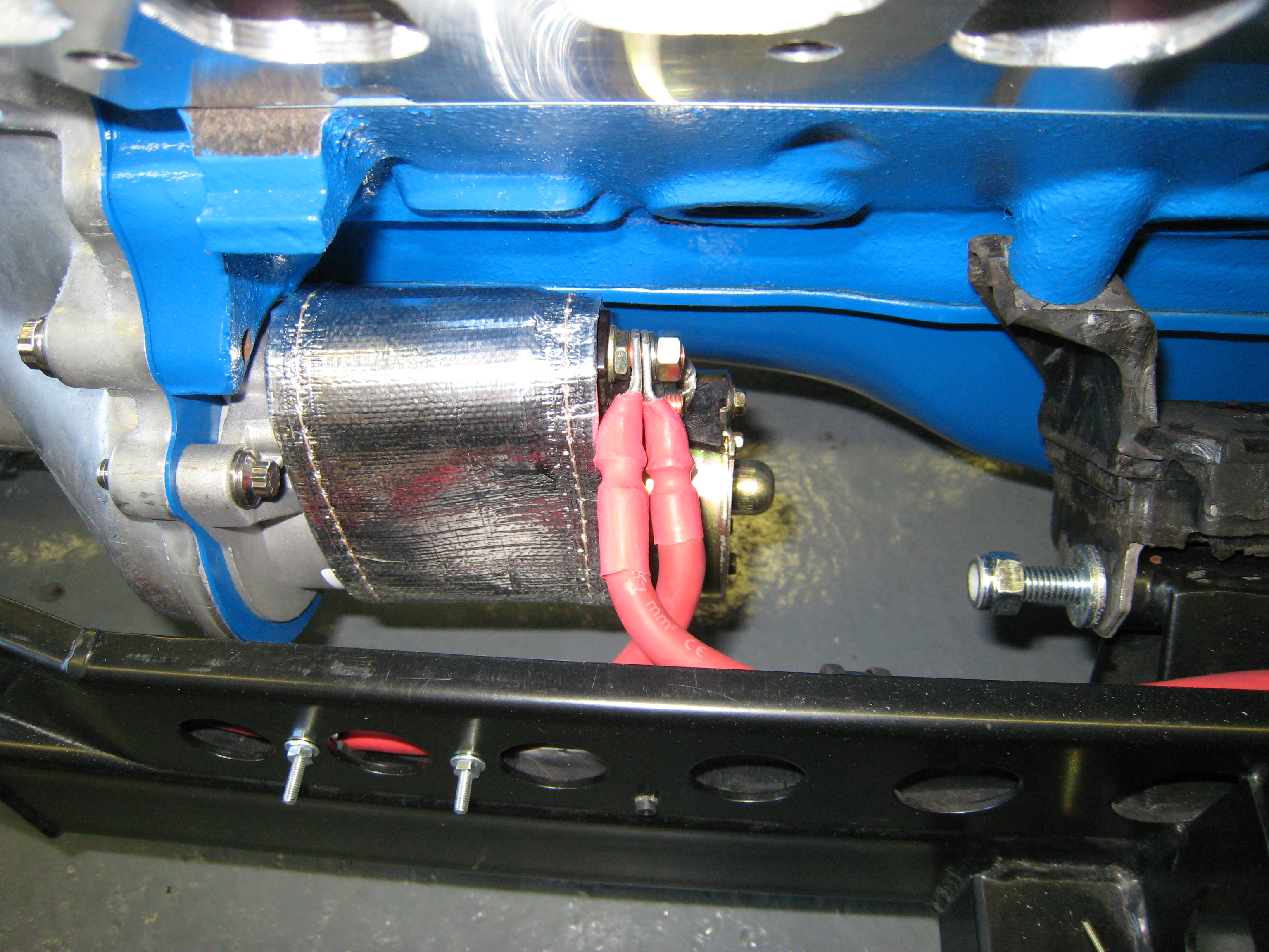
Video of starter motor test.
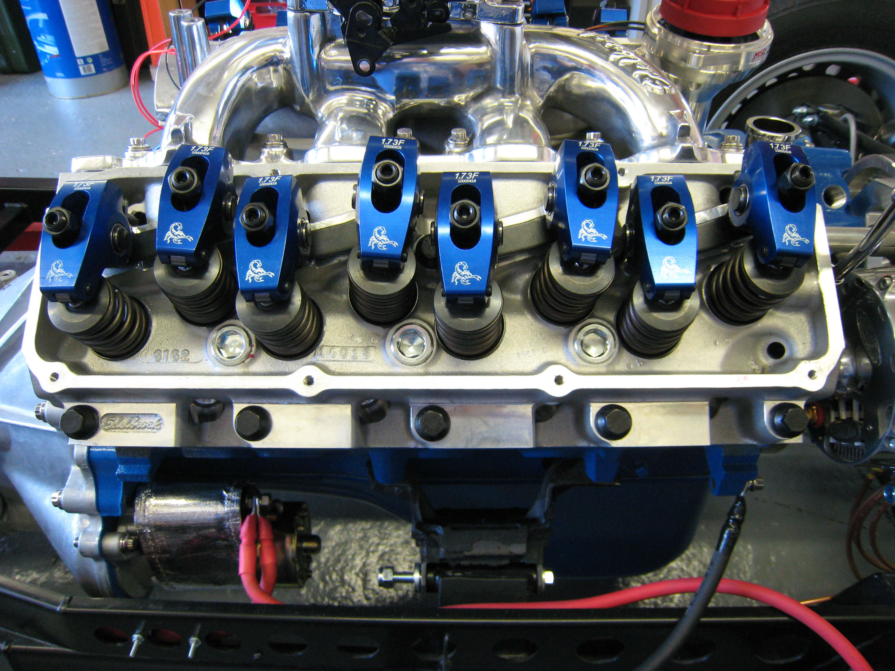
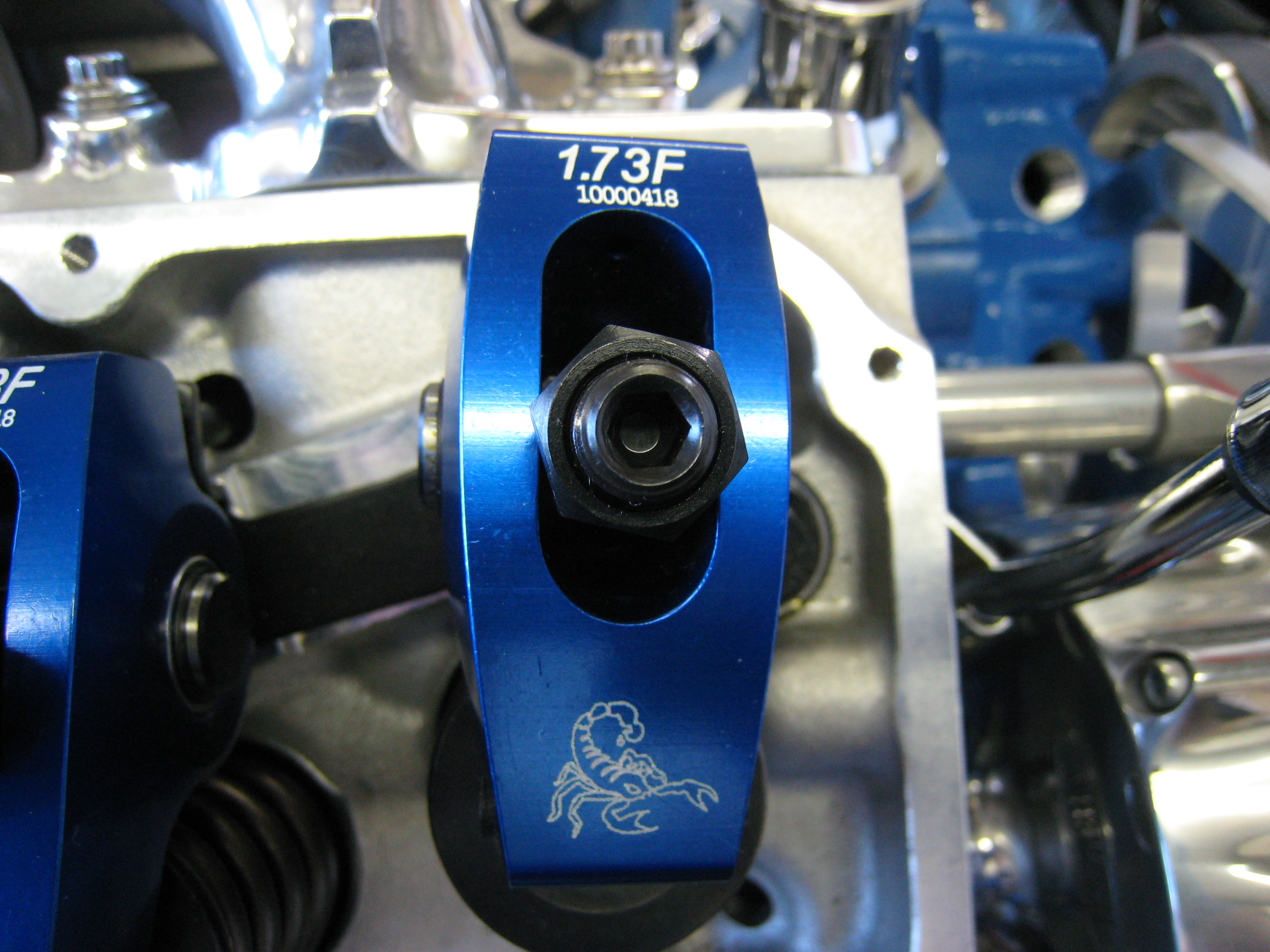
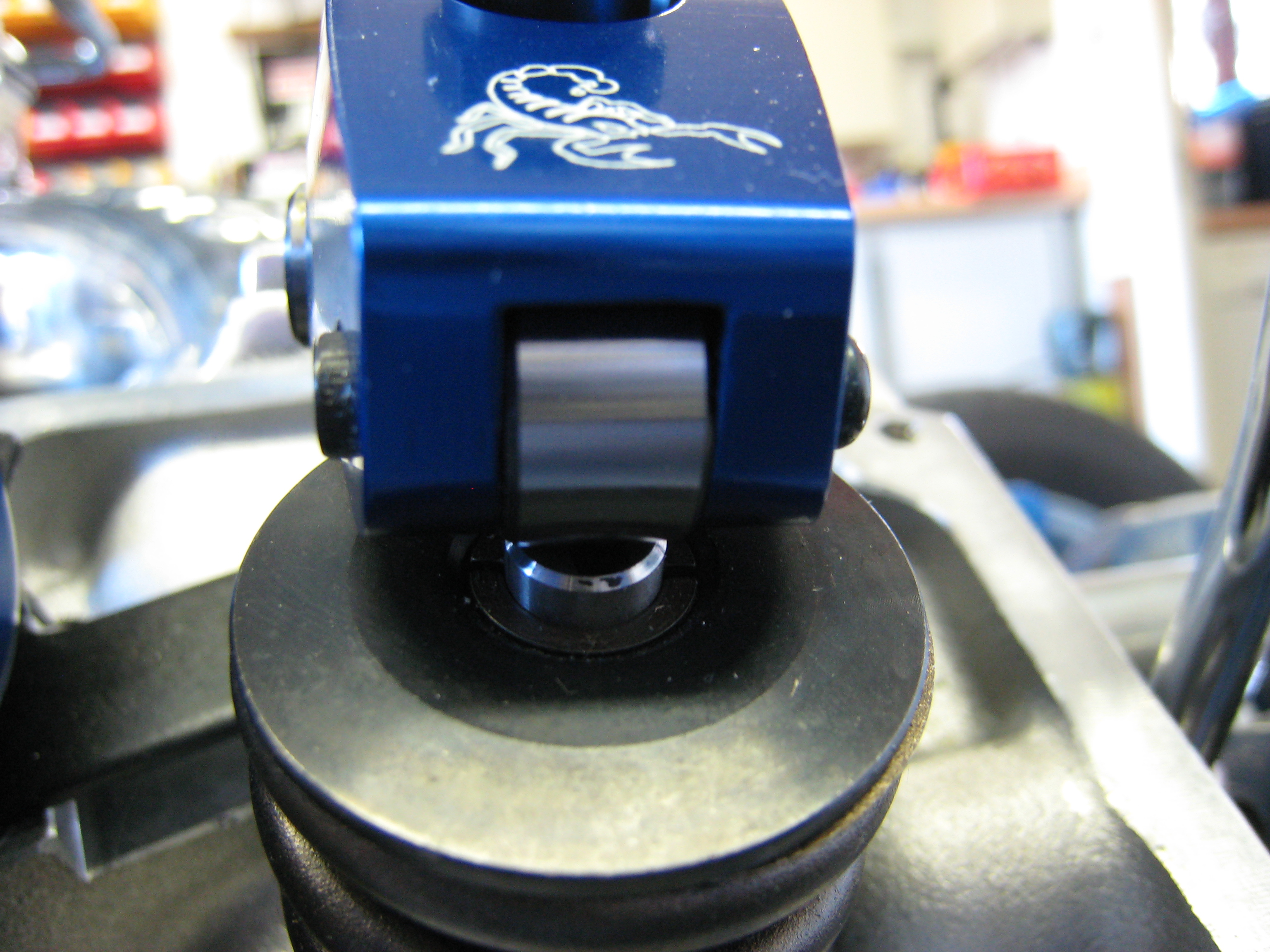
Once the starter was tested, we fitted the rather shiny rocker arms, its such a shame that they'll never been seen again.
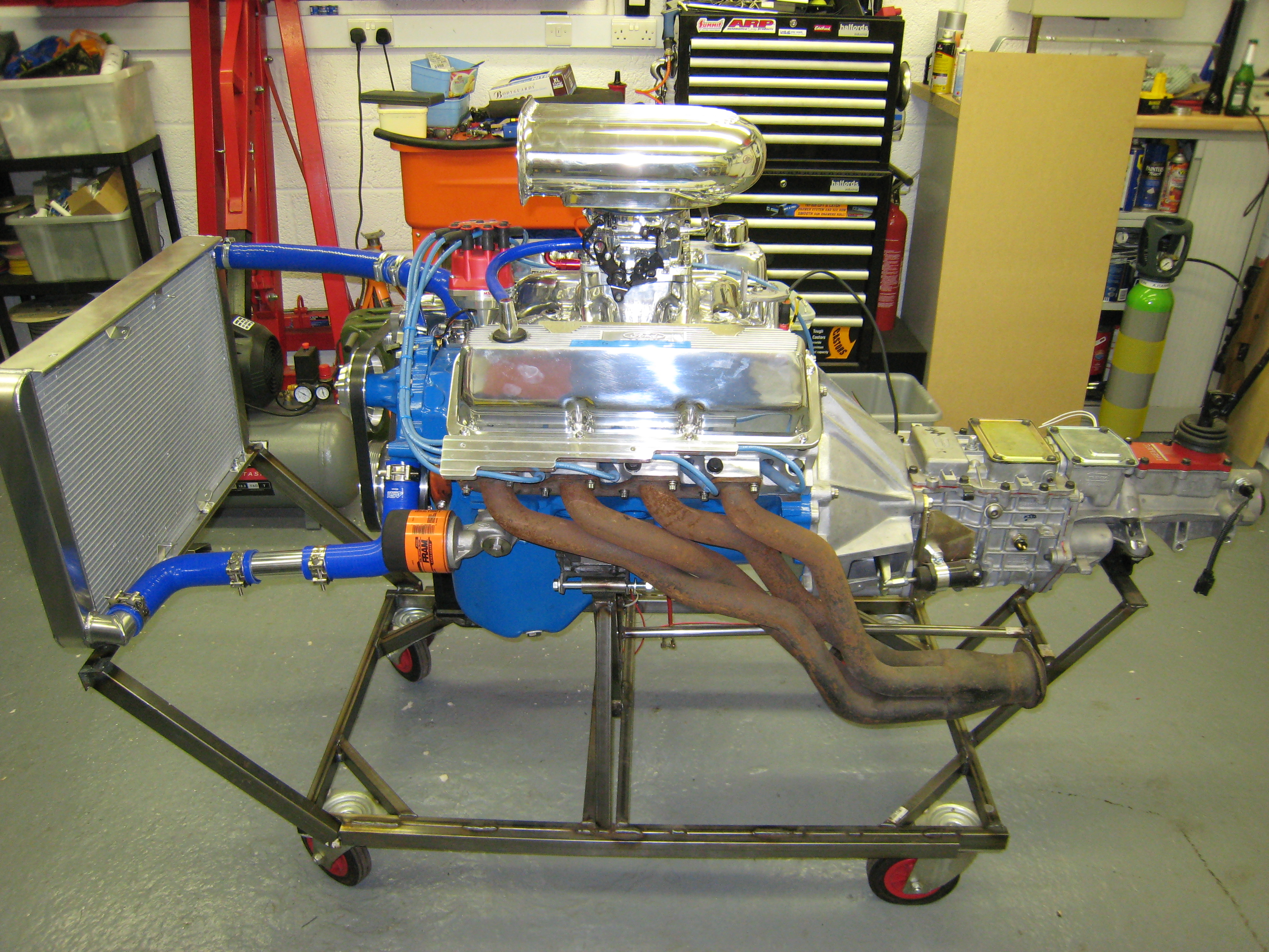
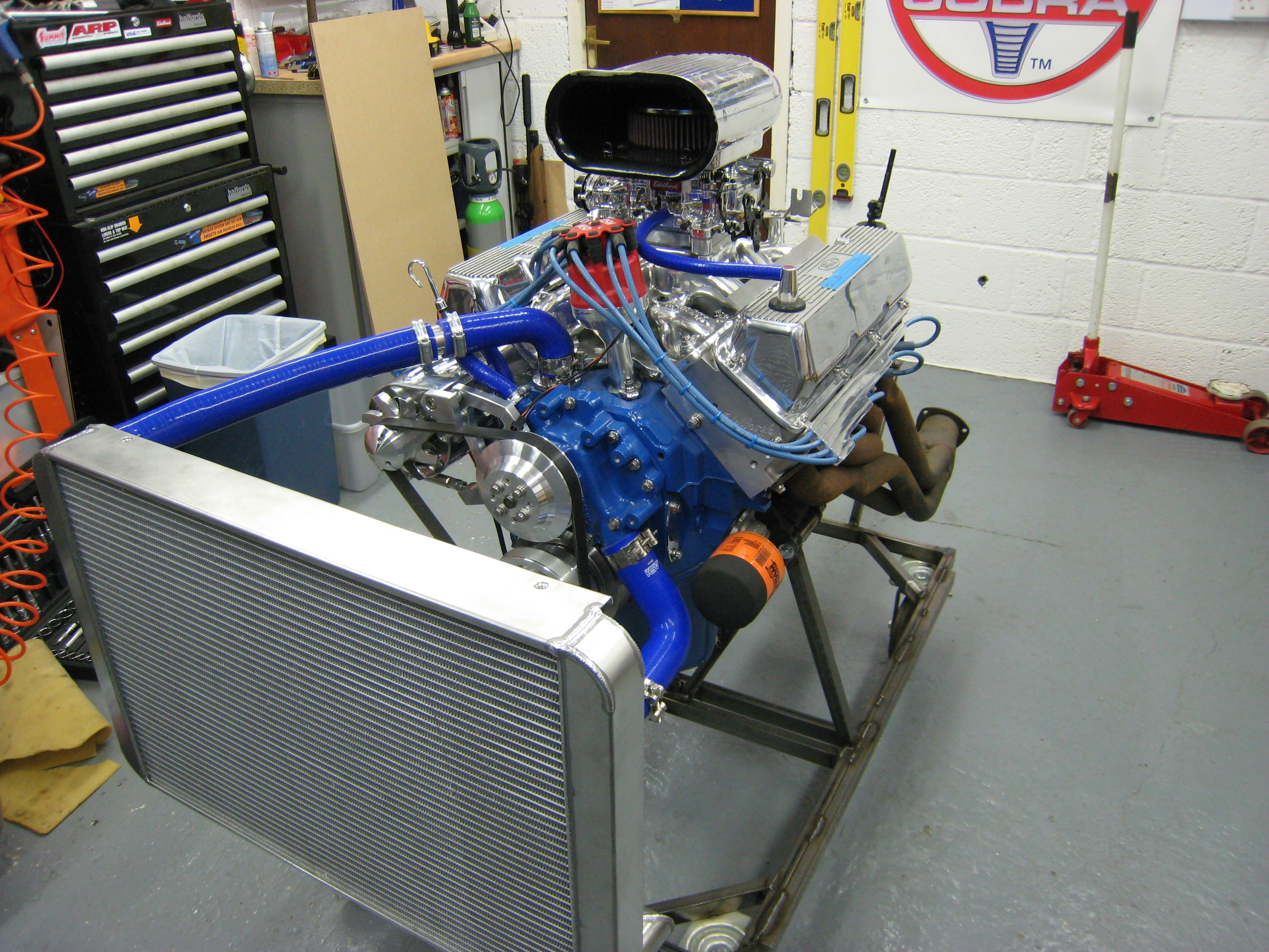
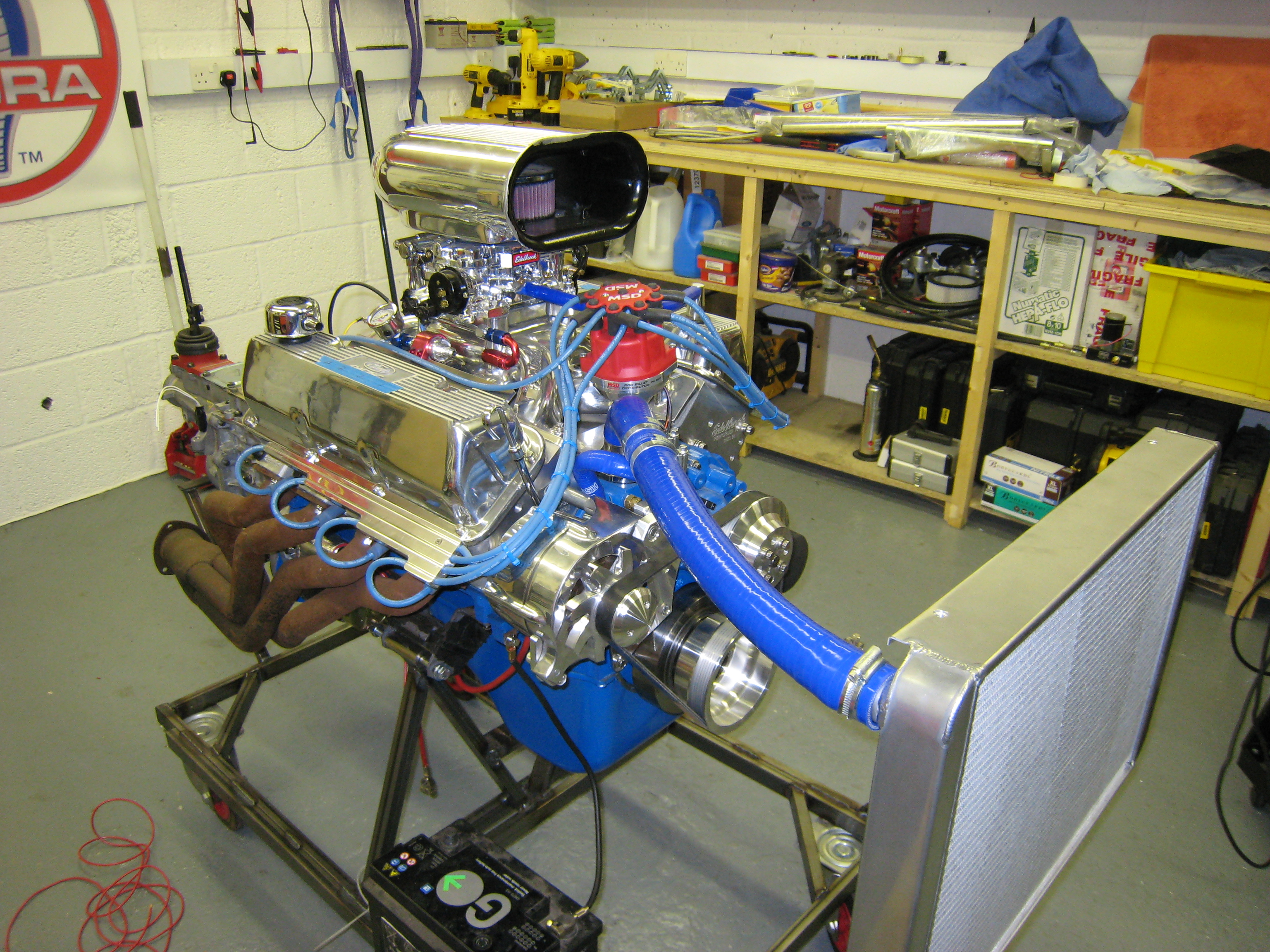
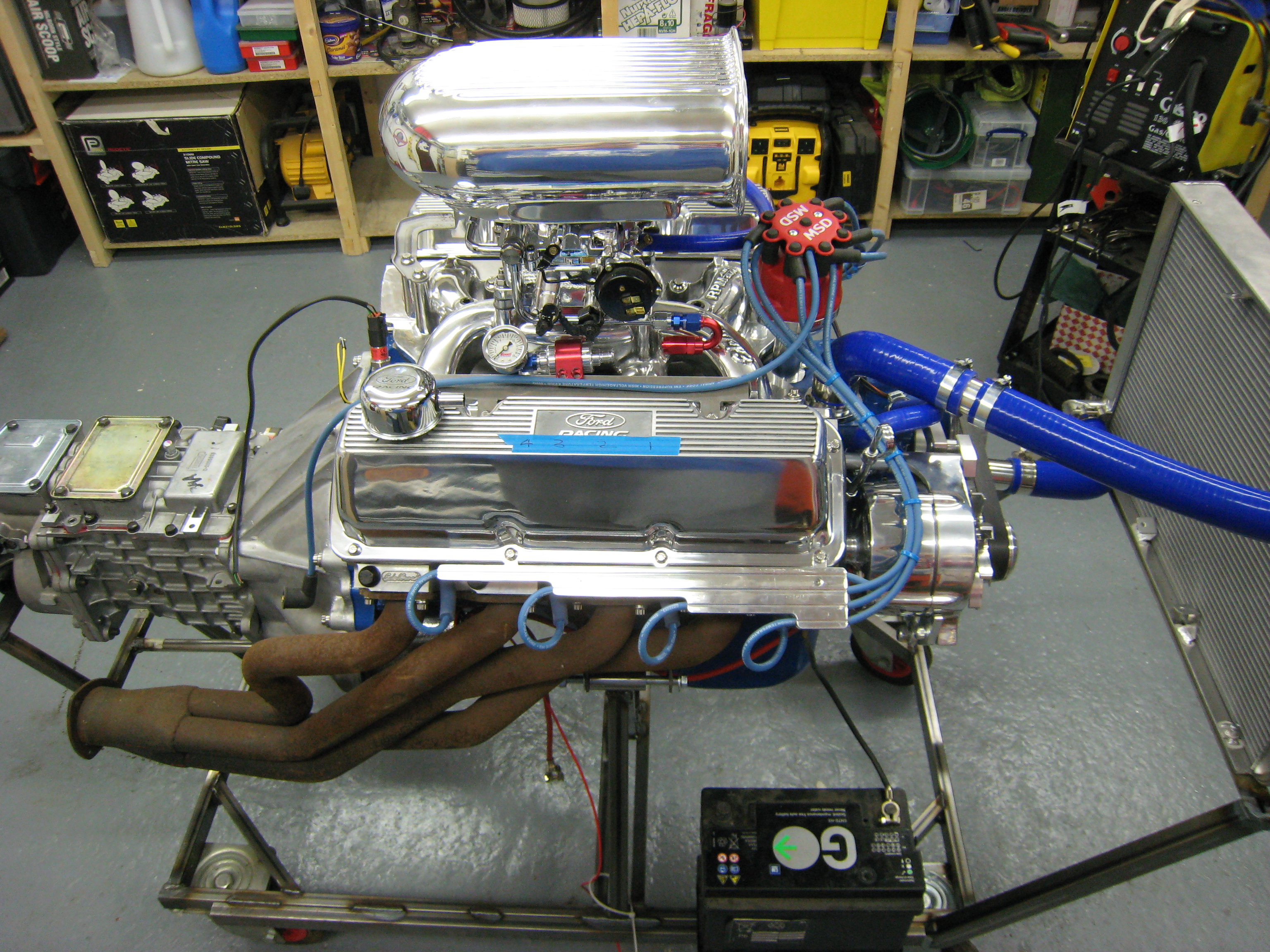
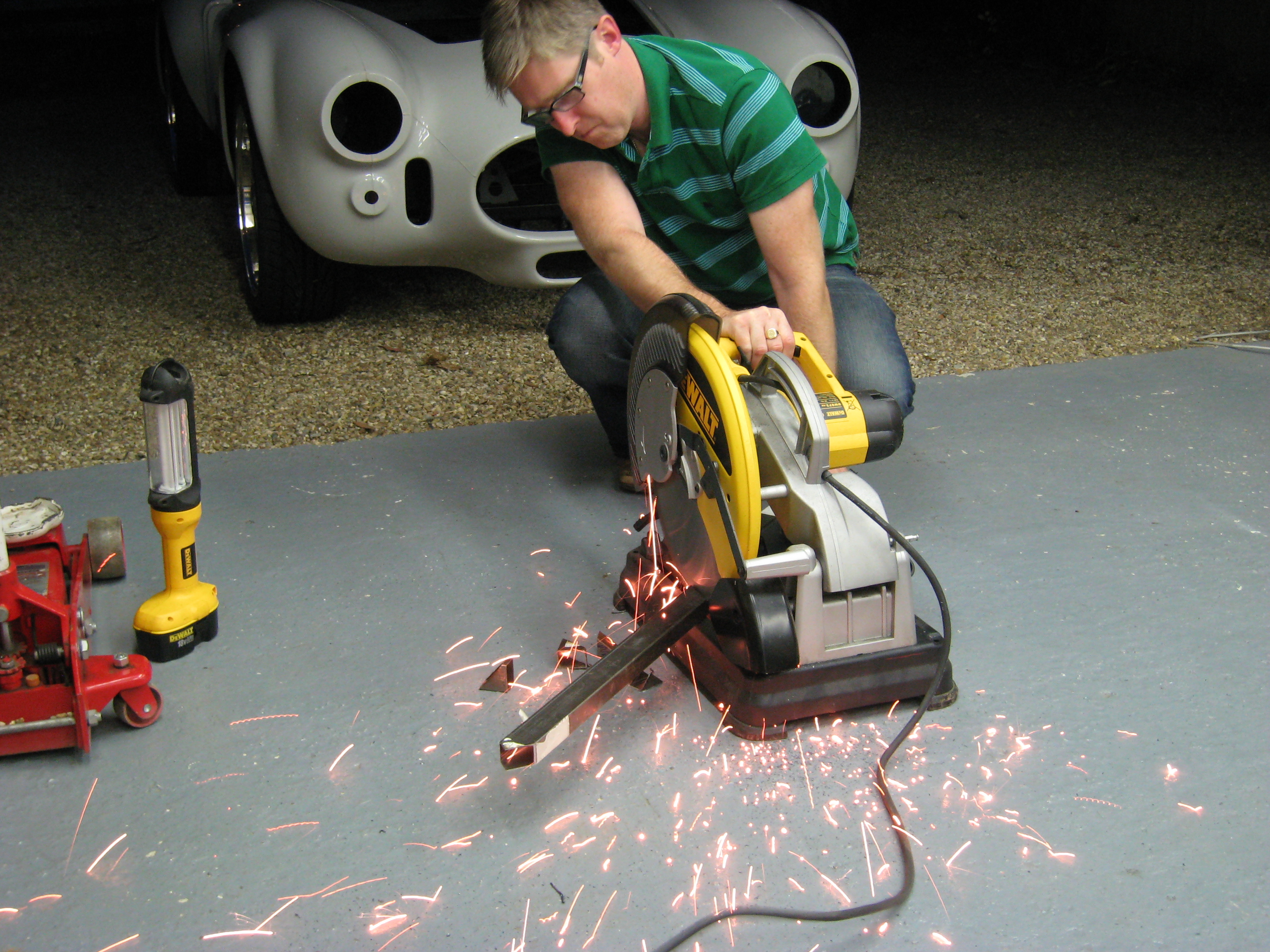
Before installing an untested engine into a very tight engine bay I thought I would be a good idea to run it in out of the car. For this Alan and I welded up a test stand. Not the most sturdy construction in the world but hopefully strong enough to hold the engine and gearbox for the 20mins its going to take to run it in.
Next comes the test stand control panel where I intend to mount all the gauges and lights to fully test all the engine electrical systems before committing them to the car.
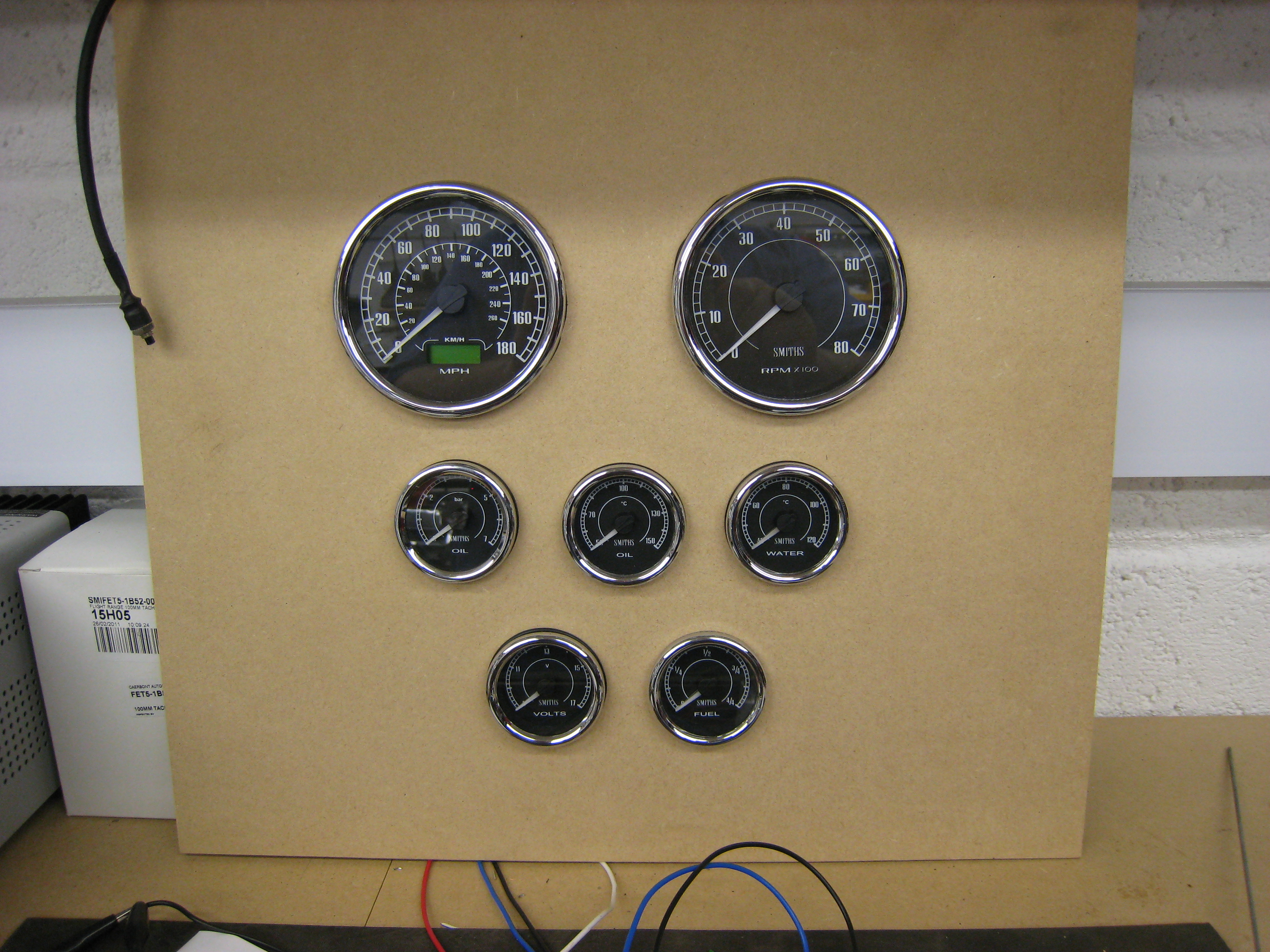
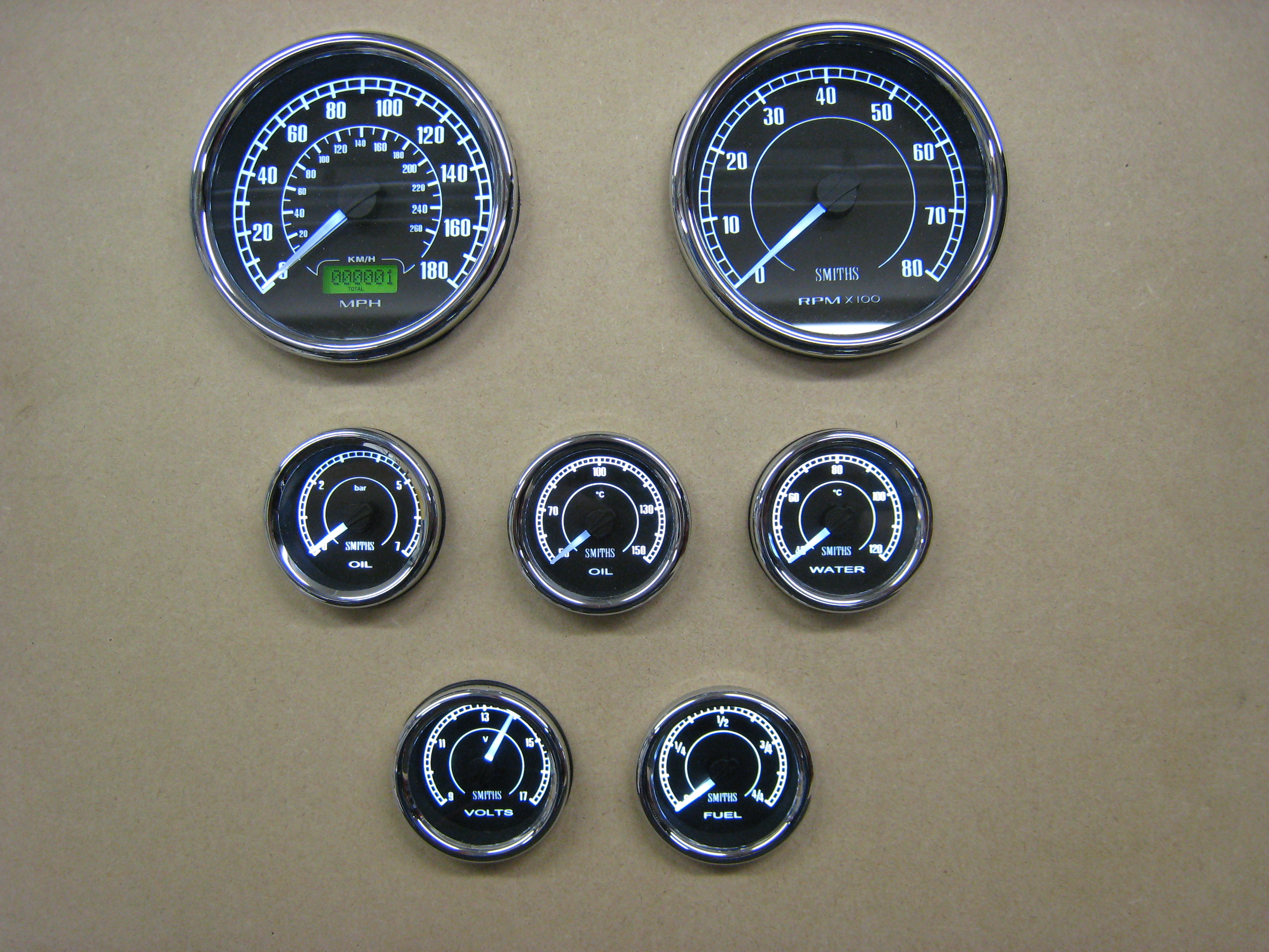
Video of gauges
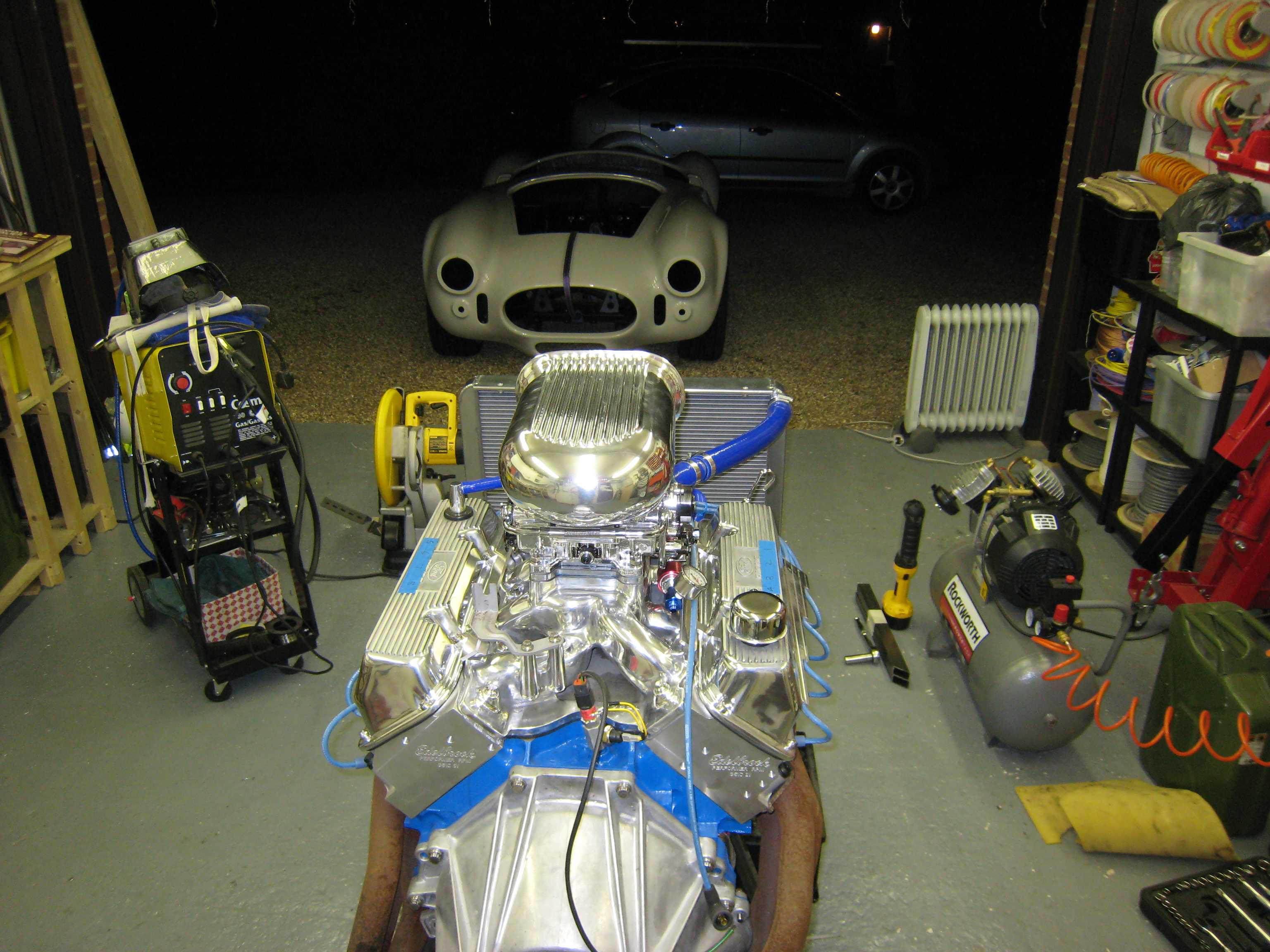
15th September 2011, 8:25pm The Test Run..... Well yes it does, not for long but that was the point, just to test to see if she fires, and she does, very loud thanks to having basically open headers. I'll run her in properly at the weekend so as not to annoy the neighbours too much !!
Video Link below of initial test flight !
End of Engine Section. Further updates will be on the Progress page.